Highway engineering-based pavement drainage device and method

A drainage device and pavement technology, applied in the direction of separation methods, chemical instruments and methods, fixed filter element filters, etc., can solve problems such as prone to nesting, affecting the concrete structure of the bridge body, and easy to block drainage pipes, etc., to achieve instant improvement The effect of reducing the discharge flow, avoiding drainage failure, and avoiding road accumulation

Active Publication Date: 2020-07-03
河南锦路路桥建设有限公司
View PDF6 Cites 6 Cited by
  • Summary
  • Abstract
  • Description
  • Claims
  • Application Information

AI Technical Summary

Problems solved by technology

[0003] Chinese patent application CN201621334208.8 discloses a pavement drainage system, which aims to provide a pavement drainage system that makes the connection between two adjacent road drainage ditches more closely connected. When connecting, firstly, the connecting plates adjacent to the two adjacent road drainage ditches are in contact with each other, and then the clamping blocks are installed on both sides of the connecting plates along the width direction of the drainage ditch body. When in conflict, the adjacent two connecting plates conflict with the side walls of the opening respectively; the drainage efficiency needs to be improved, and the drainage pipe is easy to be blocked
[0004] The existing drainage method has a small displacement. Due to the silt on the road surface, when heavy rainfall occurs, it is easy to cause the silt to block the drain outlet and the drainage pipe. Accidents such as nesting and flameout will seriously affect normal public transportation. If the viaduct has deep water for a long time, it will even affect the concrete structure of the bridge itself, accelerate the aging of the bridge body, and affect the normal service life of the bridge body.

Method used


Image

  • Highway engineering-based pavement drainage device and method
  • Highway engineering-based pavement drainage device and method
  • Highway engineering-based pavement drainage device and method

Examples


Embodiment 1

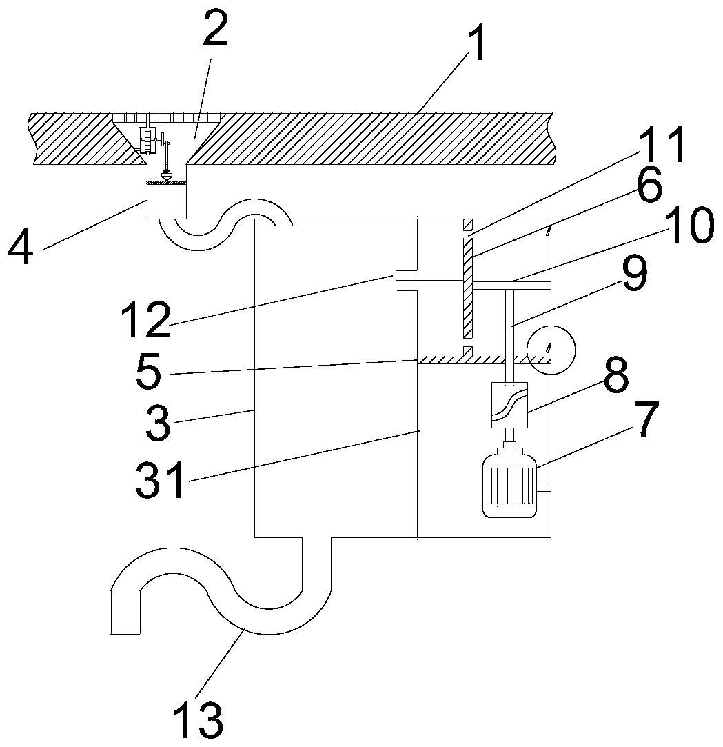
[0042] see Figure 1-6 , a pavement drainage device based on highway engineering, comprising a viaduct body 1, a water tank 2, and a housing 3; a plurality of "V"-shaped water tanks 2 are pre-embedded on both sides of the viaduct body 1, and the inside of the water tank 2 A cleaning mechanism is provided; the water guide pipe 4 is connected to the bottom of the water tank 2, the water guide pipe 4 extends to the bottom of the viaduct body 1, and the other end of the water guide pipe 4 communicates with the upper part of the housing 3; the inside of the housing 3 A booster mechanism is provided, and the housing 3 is in a closed state; the bottom of the housing 3 is provided with a downpipe 13, and a filter screen 25 is arranged inside the downpipe 13; a first Partition 31, the left side of the first partition 31 is water storage; the top of the first partition 31 is provided with an air outlet 12; A partition 5, a motor 7 is provided below the second partition 5, and the motor...

Embodiment 2

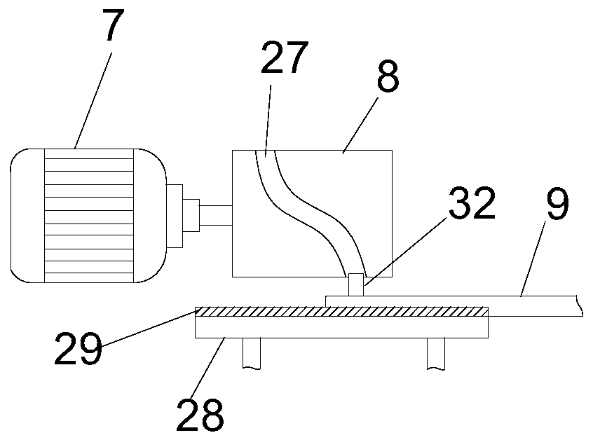
[0045] The difference from Embodiment 1 is that the cam 8 is provided with a groove 27, and the other end of the moving rod 9 is connected with a slider 32, and the slider 32 is slidably connected with the groove 27; the moving rod 9 is provided with a fixed block 28 below, and the fixed block 28 is provided with a chute 29, and the moving rod 9 is matched and slidably connected with the chute 29.

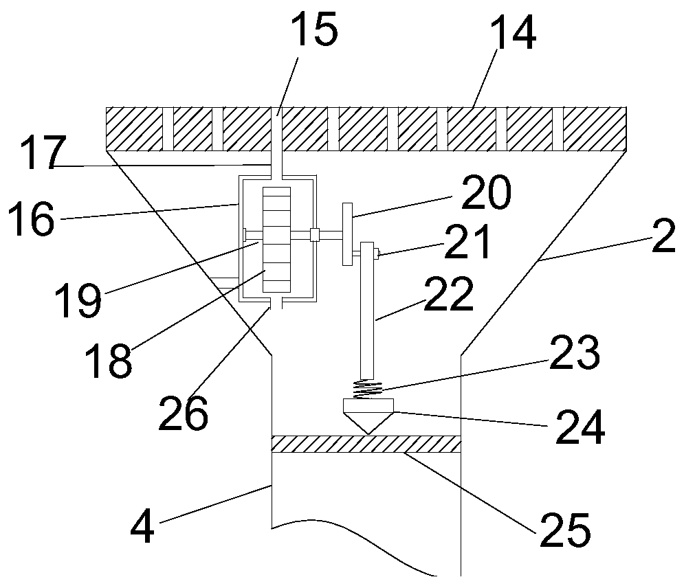
[0046] The top of the water tank 2 is provided with a grate 14, and the grate 14 is provided with a plurality of water holes 15; the cleaning mechanism includes a fixed box 16, and the fixed box 16 is connected with the water tank 2; A water inlet 17 is provided, and the water inlet 17 communicates with the water flow hole 15 , and a water outlet 26 is arranged above the fixed box 16 .

[0047] The fixed box 16 is provided with a water wheel rotor 18, the top of the water wheel rotor 18 corresponds to the water inlet 17; the middle of the water wheel rotor 18 is connected to a rota...

Embodiment 3

[0054] On the basis of Embodiments 1 and 2, in order to prevent the water level of the water storage chamber in the housing 3 from being too high, prevent water from entering the right side of the third partition 6 from the air outlet 12, and affect the normal operation of the device, the housing 3 The pressure P of the water storage chamber is greater than or equal to 3000Pa and less than or equal to 8000Pa; the viaduct height h and the diameter d of the downpipe 13 meet: h / d is greater than or equal to 100 and less than or equal to 800.

[0055] In order to further increase the drainage rate and increase the instantaneous displacement, the diameter d of the downpipe 13, the pressure P, the height of the viaduct h and the discharge rate Q satisfy the following formula:

[0056] Q=μ·πd 2 (Phv / g) 1 / 2 ;

[0057] In the above formula, the unit of d is cm; the unit of h is m; the unit of P is kPa; v is the water flow velocity of the downpipe 13, and the unit is M / s; g is the mas...


PUM


Abstract

The invention discloses a highway engineering-based pavement drainage device and method. The pavement drainage device comprises a viaduct body, gutter channels and a shell; a plurality of V-shaped gutter channels are pre-buried in the two sides of the viaduct body, and cleaning mechanisms are arranged in the gutter channels; a water guide pipe is connected to the lower portion of each gutter groove and extends to the lower portion of the viaduct body, and the other end of each gutter pipe communicates with the upper portion of the shell; and a pressurizing mechanism is arranged in the shell, and the shell is in a closed state. The cleaning mechanism is arranged in each gutter channel, so that during drainage, a filter screen is effectively cleaned, and influence of sediment deposition in the drainage process on normal drainage is prevented; the pressurizing mechanism is arranged in the shell, and a siphonic effect is formed in a water storage chamber of the shell, so that the instantaneous water discharge amount of flowing water is increased, and the water discharge rate is increased; and a certain cleaning capability is realized through a negative pressure suction effect.

Description

technical field [0001] The invention belongs to the technical field of highway engineering drainage, and in particular relates to a highway engineering pavement drainage device and method. Background technique [0002] The viaduct is an important part of the modernized urban traffic system and plays a key role in alleviating the traffic pressure in the city. The drainage performance of the viaduct has a great influence on the safety of the bridge body and the traffic safety of the viaduct. The traditional The drainage system of the viaduct mainly relies on the gravity of the water flow itself, and drainage is carried out by setting up sewer pipes. [0003] Chinese patent application CN201621334208.8 discloses a pavement drainage system, which aims to provide a pavement drainage system that makes the connection between two adjacent road drainage ditches more closely connected. When connecting, firstly, the connecting plates adjacent to the two adjacent road drainage ditches ...

Claims


Application Information

Patent Timeline
Patent Type & Authority Applications(China)
IPC IPC(8): E01D19/08B01D29/03B01D29/72
CPCB01D29/03B01D29/72E01D19/086
Inventor 毛万里吕爱伟毛喜玲师云涛郝伟焦攀飞高倩雷小江张团飞刘岩郑洁刘小明
Owner 河南锦路路桥建设有限公司
Why Eureka
Try Eureka