Gating tube material, gating tube unit and memory device structure
A technology of memory device and gate tube, applied in electrical components and other directions, can solve the problems of high toxicity of materials, large leakage current, small gate ratio, etc.
- Summary
- Abstract
- Description
- Claims
- Application Information
AI Technical Summary
Problems solved by technology
Method used
Image
Examples
Embodiment 1
[0047] This embodiment provides a gate material, which is a compound including at least Ge (germanium) and S (sulfur), and the general chemical formula of the gate material is (Ge x S 1-x ) 1-y m y , wherein M includes doping materials, and 0.1≤x≤0.9, 0≤y≤0.5.
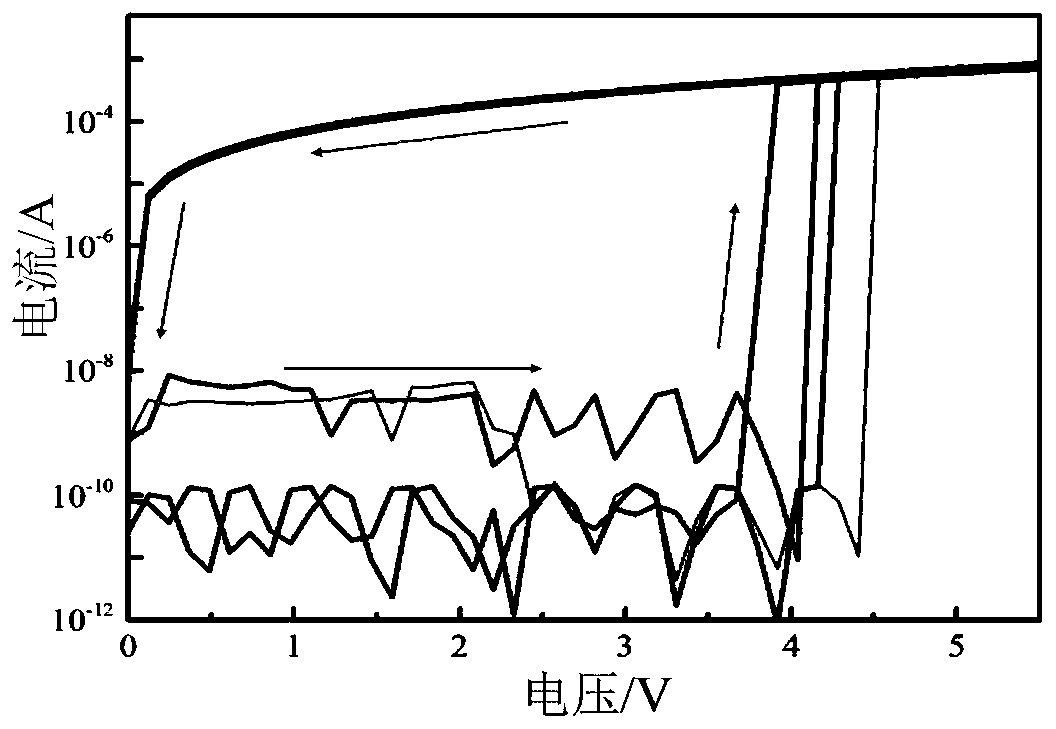
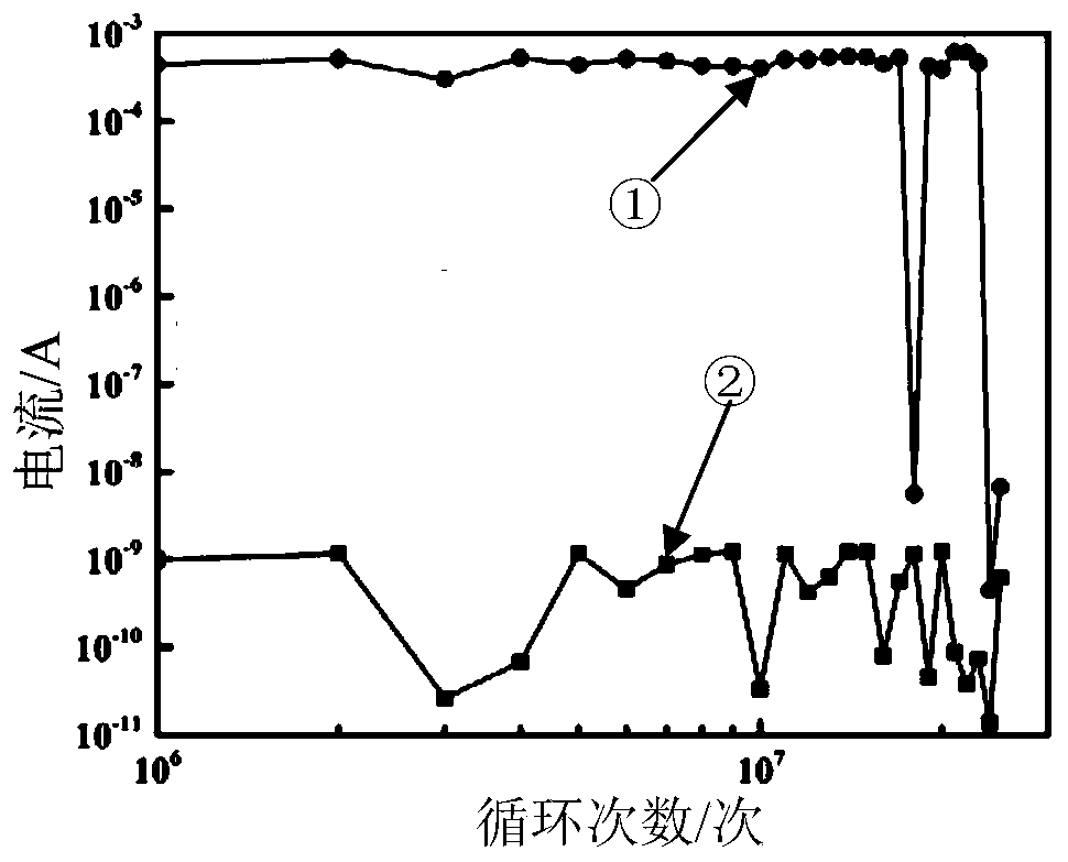
[0048] The value of y in the general chemical formula of the gating tube material can be 0, that is, the gating tube material does not contain doping materials, that is, the gating tube material is a compound including Ge and S at this time , the general chemical formula of the gating tube material is Ge x S 1-x , 0.1≤x≤0.9. The material of the gate tube at this time has an opening current I when it is used for the gate tube unit on Large, leakage current I off Small, gate ratio (I on / I off ) large, good thermal stability, simple material and non-toxic.
[0049] The value of y in the general chemical formula of the gating tube material may not be zero, that is, the gating tube material contains a doping mate...
Embodiment 2
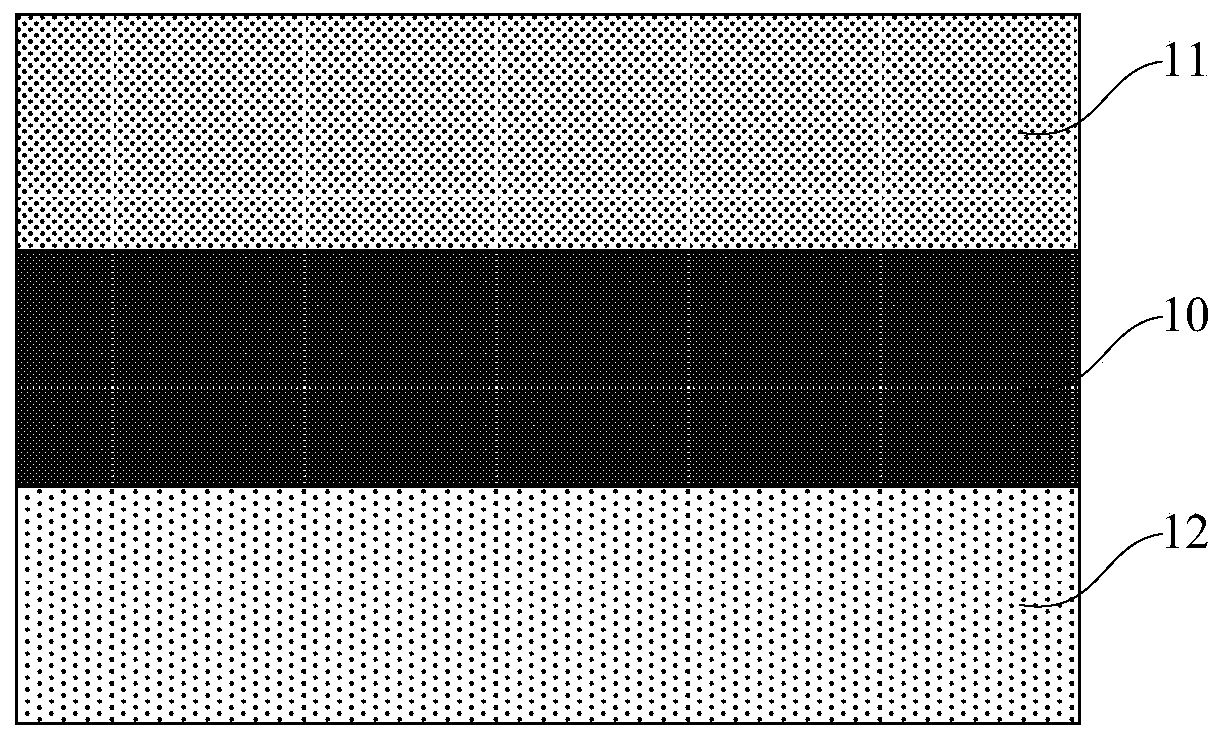
[0058] see figure 1 , the present invention also provides a gating tube unit, the gating tube unit includes: a gating tube material layer 10, a first electrode 11 and a second electrode 12; wherein,
[0059] The gate material layer 10 includes the gate material as described in Embodiment 1, that is, the gate material layer 10 is a material layer prepared from the gate material as described in Embodiment 1; For the composition of the gate material layer 10, please refer to Embodiment 1, which will not be repeated here;
[0060] The first electrode 11 is located on the upper surface of the gate material layer 10;
[0061] The second electrode 12 is located on the lower surface of the gate material layer 10 .
[0062] As an example, the gate material layer 10 may be formed by, but not limited to, a magnetron sputtering process.
[0063] As an example, the thickness of the gate material layer 10 can be set according to actual needs. Preferably, the thickness of the gate materia...
Embodiment 3
[0074] see Figure 6 and Figure 7 , the present embodiment provides a storage device structure, and the present invention also provides a storage device structure, the storage device structure comprising: the gate unit as described in the second embodiment, the storage material layer 13 and the third electrode 14; Wherein, for the specific structure of the gate unit, please refer to Embodiment 2, which will not be repeated here; the storage material layer 13 is located on the lower surface of the second electrode 12; the third electrode 14 is located on the The lower surface of the storage material layer 14. At this time, the first electrode 11 is used as an upper electrode, the second electrode 12 is used as a middle electrode, and the third electrode 14 is used as a lower electrode.
[0075] As an example, the thickness of the second electrode 12 may be set according to actual needs. Preferably, in this embodiment, the thickness of the second electrode 12 may include 5 nm...
PUM
| Property | Measurement | Unit |
|---|---|---|
| thickness | aaaaa | aaaaa |
| thickness | aaaaa | aaaaa |
| thickness | aaaaa | aaaaa |
Abstract
Description
Claims
Application Information
 - R&D
- Intellectual Property
- Life Sciences
- Materials
- Tech Scout
- Unparalleled Data Quality
- Higher Quality Content
- 60% Fewer Hallucinations
Browse by: Latest US Patents, China's latest patents, Technical Efficacy Thesaurus, Application Domain, Technology Topic, Popular Technical Reports.
© 2025 PatSnap. All rights reserved.Legal|Privacy policy|Modern Slavery Act Transparency Statement|Sitemap|About US| Contact US: help@patsnap.com


