Adaptive landing deck control system and method for rotor-like aircraft

A control method and self-adaptive technology, applied in aircraft parts, motor vehicles, aircraft, etc., can solve the problems of difficult to control the high precision and high precision of mechanical structures, the dynamic response speed of the system does not meet the requirements, and the motion reduction effect is general. , to achieve the effect of novel structure, strong anti-interference ability and large load weight

Active Publication Date: 2022-08-05
NANJING UNIV OF AERONAUTICS & ASTRONAUTICS +1
View PDF6 Cites 0 Cited by
  • Summary
  • Abstract
  • Description
  • Claims
  • Application Information

AI Technical Summary

Problems solved by technology

[0004] This kind of stable platform with two-axis structure is driven by a servo motor. Since there is a single point of force between the support frame and the platform, once the load mass on the platform is large or the mass distribution is uneven, the entire mechanism will be affected by the frame mass. Factors such as unbalanced torque, frictional interference torque between shafts, and mechanical structure resonance are seriously affected, as well as random errors and noises of the gyroscope, which are important reasons that affect the inertial stability accuracy of the system. In addition to the difficulty in controlling the high precision of the mechanical structure and machining In addition to the high precision of the installation, it is also difficult to improve the dynamic and static stability performance indicators of the system through effective control strategies. The reason is that the dual-axis servo motor has a general effect on reducing the motion of the carrier (hull) itself, and the dynamic response speed of the system is up to It does not meet the requirements, and the actual application effect is mediocre. This structure is generally only used in scenes where the base is a fixed still life. It is difficult to use this structure on ships.

Method used


Image

  • Adaptive landing deck control system and method for rotor-like aircraft
  • Adaptive landing deck control system and method for rotor-like aircraft
  • Adaptive landing deck control system and method for rotor-like aircraft

Examples


Embodiment Construction

[0034] The following describes the implementation of the invention in detail. The example of the embodiment is shown in the attached figure. The same or similar label from beginning to end indicates the same or similar components or components with the same or similar function. The embodiments described by reference to the attachment are examples, only to explain the present invention, and cannot be interpreted as the restrictions on the invention.

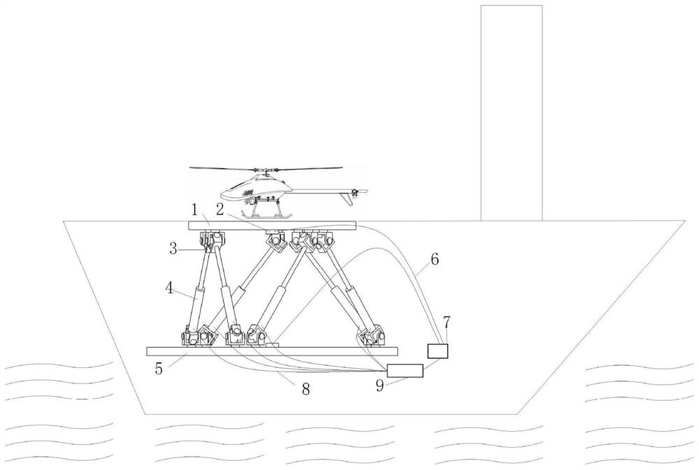
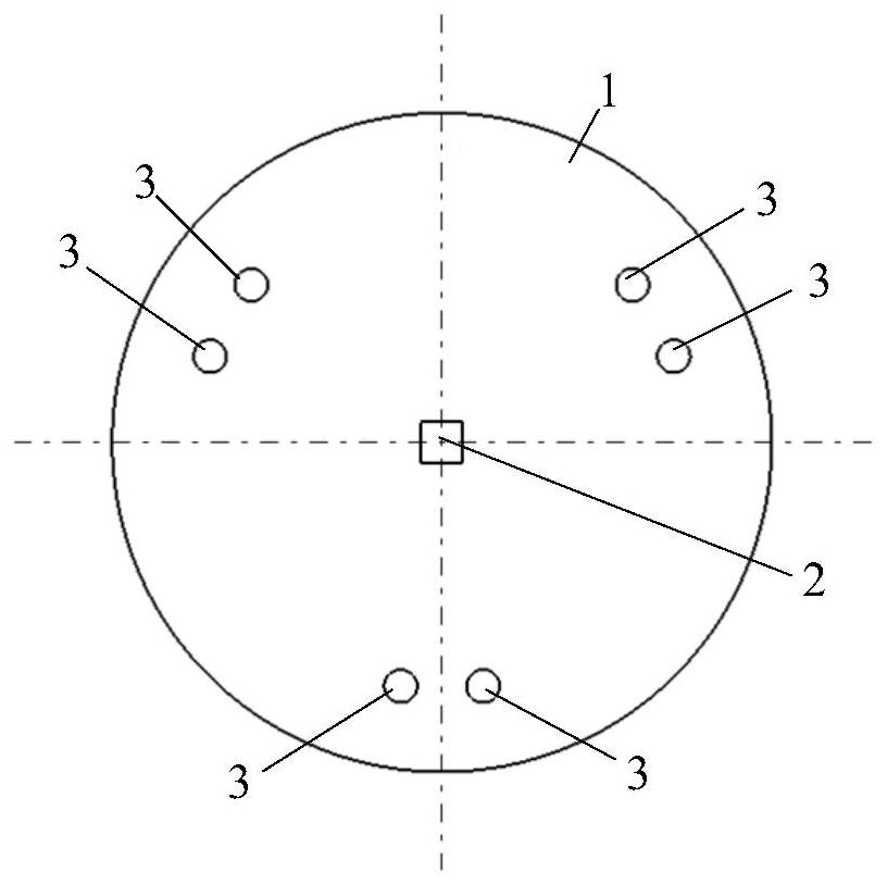
[0035] like figure 2 It shows that the present invention provides a self -adaptive rotor aircraft landing deck system, including landing deck 1, MEMS gyroscope 2, Hu Ke hinge 3, hydraulic control valve 4, base 5, data line 6, ECU control center 7, signal signal, signal Line 8, hydraulic controller 9. like image 3 It shows, the bottom surface of the landing deck 1 is installed with six Tiger Hed Hinges 3, and the six tiger cord hinges 3 points are evenly distributed in three sets in the center of the landing deck 1 as the center of the...


PUM


Abstract

The invention discloses a self-adaptive landing deck control system and method for a rotor-type aircraft. The system includes a base, a landing deck, a MEMS gyroscope, a Hook hinge, a hydraulic control valve, an ECU control center and a hydraulic controller. Three sets of Hooke hinges are evenly distributed along the circumference of the bottom surface of the landing deck. Three groups of Hooke hinges are evenly distributed along the circumference on the upper surface of the base. The base is mounted on the hull of the ship. Hook hinge groups on landing deck and base are staggered. The top end of the push rod of the hydraulic valve is connected to the landing deck through the Hook hinge, and the bottom end is connected to the base through the Hook hinge. Two MEMS gyroscopes are mounted on the landing deck and the base, respectively. When the aircraft lands, the signal of the MEMS gyroscope is transmitted to the ECU control center. After calculation, the control center transmits the instruction to the hydraulic controller. The hydraulic controller sends instructions to each hydraulic valve to adjust the length of the push rod of each hydraulic valve, so as to maintain the landing. The deck is always level and raised above the deck of the ship and maintains the same altitude. The system of the invention has stable performance and high control precision.

Description

Technical field [0001] The invention involves a rotor aircraft adapted to the falling deck control system and methods, which belongs to the horizontal stable technology field of rotor aircraft on the small and medium -sized carrier. Background technique [0002] With the development of the drone market in recent years, the rotor drone has quickly won the attention and love of consumer groups with the advantages of excellent control performance and the convenience of vertical take -off and landing. At present, the application of land -based rotor drones is very wide, but there are not many applications of carrier rotor drones. The main reason is that the rotor drone is very difficult to land on the shaking ship. Affected by the waves with the ship, it caused the posture to be unprecedented, and the unsuccessful incident of landing and slipping on the side caused major accidents such as the crash or the damage of the ship, and the casualties of the ship. Therefore, how to make the ...

Claims


Application Information

Patent Timeline
Patent Type & Authority Patents(China)
IPC IPC(8): B64F1/00
CPCB64F1/00B64U10/10B64U70/00
Inventor 周福亮聂宏魏小辉汤为伟丁林
Owner NANJING UNIV OF AERONAUTICS & ASTRONAUTICS
Why Eureka
Try Eureka