
An air treatment device in the production process of carbon fiber precursor and its application

An air treatment device and carbon fiber precursor technology, which is applied in the field of chemical fiber production, can solve the problems of fiber strength and quality, increase filament winding and broken filament, and affect oiling effect, so as to avoid local overheating, reduce replacement frequency, and reduce The effect of oil consumption

Active Publication Date: 2021-06-22
山西钢科碳材料有限公司 +1
View PDF4 Cites 0 Cited by
  • Summary
  • Abstract
  • Description
  • Claims
  • Application Information

AI Technical Summary

Problems solved by technology

If the oil used is a silicone oil, it is possible that the local oil will undergo cross-linking due to the high temperature of the fiber after hot water drawing, and the viscosity will increase greatly, forming a substance similar to an adhesive, which adheres to the fiber. Increases the probability of entanglement and filament breakage, affecting fiber performance
Secondly, there are many carbon fiber precursors in the production process, and multiple spinning positions are produced at the same time, and a bundle of fibers in each spinning position contains tens of thousands of monofilaments. The fibers are coagulated, washed, and drawn in hot water. Under the impact of water flow and external forces such as drafting roller tension, it is easy to parallel, intertwine, and twist, which affects the uniform fiber formation and oiling effect, resulting in an impact on fiber strength and quality.

Method used


Image

  • An air treatment device in the production process of carbon fiber precursor and its application
  • An air treatment device in the production process of carbon fiber precursor and its application
  • An air treatment device in the production process of carbon fiber precursor and its application

Examples


Embodiment 1

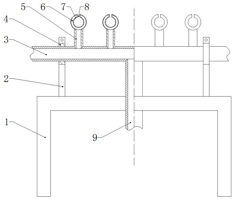
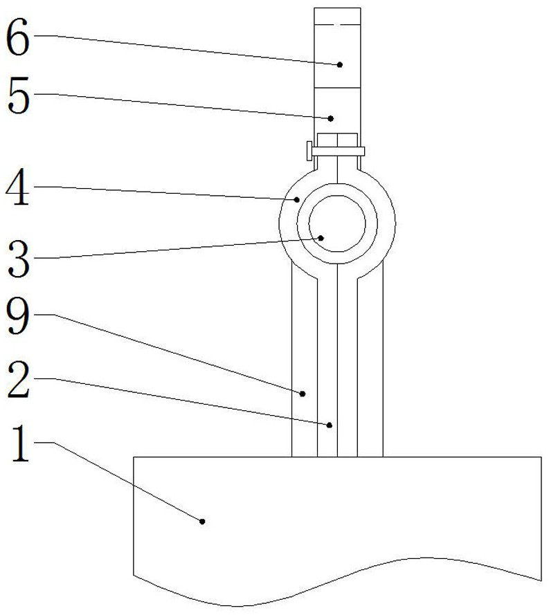
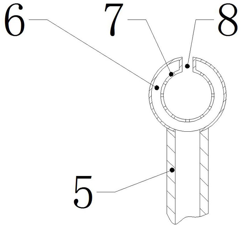
[0024] Such as Figure 1 to Figure 3 As shown, the air treatment device provided in Example 1 is applied to wet spinning of polyacrylonitrile-based carbon fiber precursors.

[0025] Tighten the lower end of the gas transmission branch pipe 5 with raw material tape, and then connect it to the corresponding threaded port of the gas transmission main pipe 3. The gas transmission main pipe 3 is fixed on the workbench 1 through the bracket 2 and the collar 4. The diameter of the gas transmission main pipe 3 is 20mm , the lower part of the gas delivery main pipe 3 is connected to the intake pipe 9, and the ports at both ends of the gas delivery main pipe 3 are closed. The inner diameter of the air blowing ring 6 is 10 mm, the outer diameter is 15 mm, and eight air injection ports 7 are evenly distributed around the inner circle, and the aperture of the air injection ports 7 is 1 mm. The upper end of the blowing ring 6 is provided with a diversion notch 8, the width of the diversion...

Embodiment 2

[0029] Such as Figure 1 to Figure 3 As shown, the air treatment device provided in Example 2 is applied to dry-jet wet spinning of polyacrylonitrile-based carbon fiber precursors.

[0030] The gas delivery branch pipe 5, the gas delivery main pipe 3 and the blowing ring 6 are integrally formed. The gas delivery main pipe 3 is fixed on the workbench 1 through the bracket 2 and the collar 4. The diameter of the gas delivery main pipe 3 is 25 mm. Connect the inlet pipe 9, and the two ends ports of the gas delivery main pipe 3 are closed. The inner diameter of the air blowing ring 6 is 15 mm, the outer diameter is 20 mm, and 10 air jets 7 are evenly distributed around the inner circle, and the diameter of the air jets 7 is 1 mm. The upper end of the blowing ring 6 is provided with a diversion gap 8, the width of the diversion gap 8 is 4mm, and the lower side of the blowing ring 6 is connected to the gas delivery branch pipe 5, and the diameter of the gas delivery branch pipe 5 i...


PUM

PropertyMeasurementUnit
diameteraaaaaaaaaa
diameteraaaaaaaaaa

Abstract

An air treatment device in the production process of carbon fiber raw silk and its application, belonging to the technical field of chemical fiber production, prolonging the service life of the oil agent, reducing the frequency of oil agent replacement, increasing the output and pass rate of the raw silk, and facilitating uniform oiling and steam drafting The plasticizing effect is beneficial to improve the quality and uniformity of the raw silk. The device includes a workbench, a bracket, an air intake pipe, a main gas delivery pipe and a gas delivery branch pipe. The upper part of the bracket is provided with a collar, the main gas delivery pipe is arranged horizontally and snapped into the collar, and the lower part of the main air delivery pipe is connected with the intake pipe. There are a number of branch gas pipes above the main gas pipe. The position of the branch pipes corresponds to the spinning position of the carbon fiber precursor. A blowing ring is set above the branch pipes. The inner cavity of the blowing ring passes through the branch pipes and the The main pipe is connected, and the inner surface of the air blowing ring is evenly distributed along the circumferential direction with an even number of air injection ports; the air treatment device is set at a position 0.5m-2m in front of the upper oil tank, and the air treatment device is set at a position 0.5m-2m in front of the steam drawing furnace 2m position.

Description

technical field [0001] The invention belongs to the technical field of chemical fiber production, and in particular relates to an air treatment device in the production process of carbon fiber precursors and its application. Background technique [0002] Carbon fiber is a high-performance special fiber widely used in key fields such as aerospace and high-end civilian fields. Now it has formed a pivotal new material system, and it is still developing strongly, with a large market space and application prospects. In recent years, with the strong support of the state and the participation of powerful enterprises, my country's carbon fiber business has made great progress. However, compared with developed countries, we still have a big gap in product stability, reliability and economy. . As the precursor fiber of high-performance carbon fiber, the quality of the precursor directly affects the quality of carbon fiber, which is the bottleneck restricting the development of carbon ...

Claims


Application Information

Patent Timeline
Patent Type & Authority Patents(China)
IPC IPC(8): D01D11/02D01D10/06
CPCD01D10/06D01D11/02
Inventor 韩笑笑常春报刘纳新郝俊杰孙立新李晋虎马跃文
Owner 山西钢科碳材料有限公司
Learn More