Method for testing contact resistivity of passivated contact structure

A technology of contact resistivity and contact structure, which is applied in the field of solar cells, can solve the problems of complex photolithography mask process and RIE process, difficulty in mass production, and long time consumption, and achieve simple preparation process, good accuracy, short time effect

Active Publication Date: 2020-07-10
TAIZHOU ZHONGLAI PHOTOELECTRIC TECH CO LTD
View PDF6 Cites 2 Cited by
  • Summary
  • Abstract
  • Description
  • Claims
  • Application Information

AI Technical Summary

Problems solved by technology

Although the above two methods can eliminate the interference of redundant transmission paths and accurately test the contact resistivity, the photolithography mask process and RIE process have the disadvantages of complex process, high cost, time-consuming and difficult to produce samples in large quantities. Difficult to use in

Method used


Image

  • Method for testing contact resistivity of passivated contact structure
  • Method for testing contact resistivity of passivated contact structure
  • Method for testing contact resistivity of passivated contact structure

Examples


Embodiment Construction

[0051] Below in conjunction with example the present invention is described in detail.

[0052] The specific embodiment is only an explanation of the present invention, not a limitation of the present invention. Those skilled in the art can make modifications without creative contribution to the present embodiment as required after reading this description, but as long as they are within the scope of the claims of the present invention inside are protected.

[0053] A kind of method for testing the contact resistivity of passivation contact structure of the present invention, its technical scheme is: comprise the following steps:

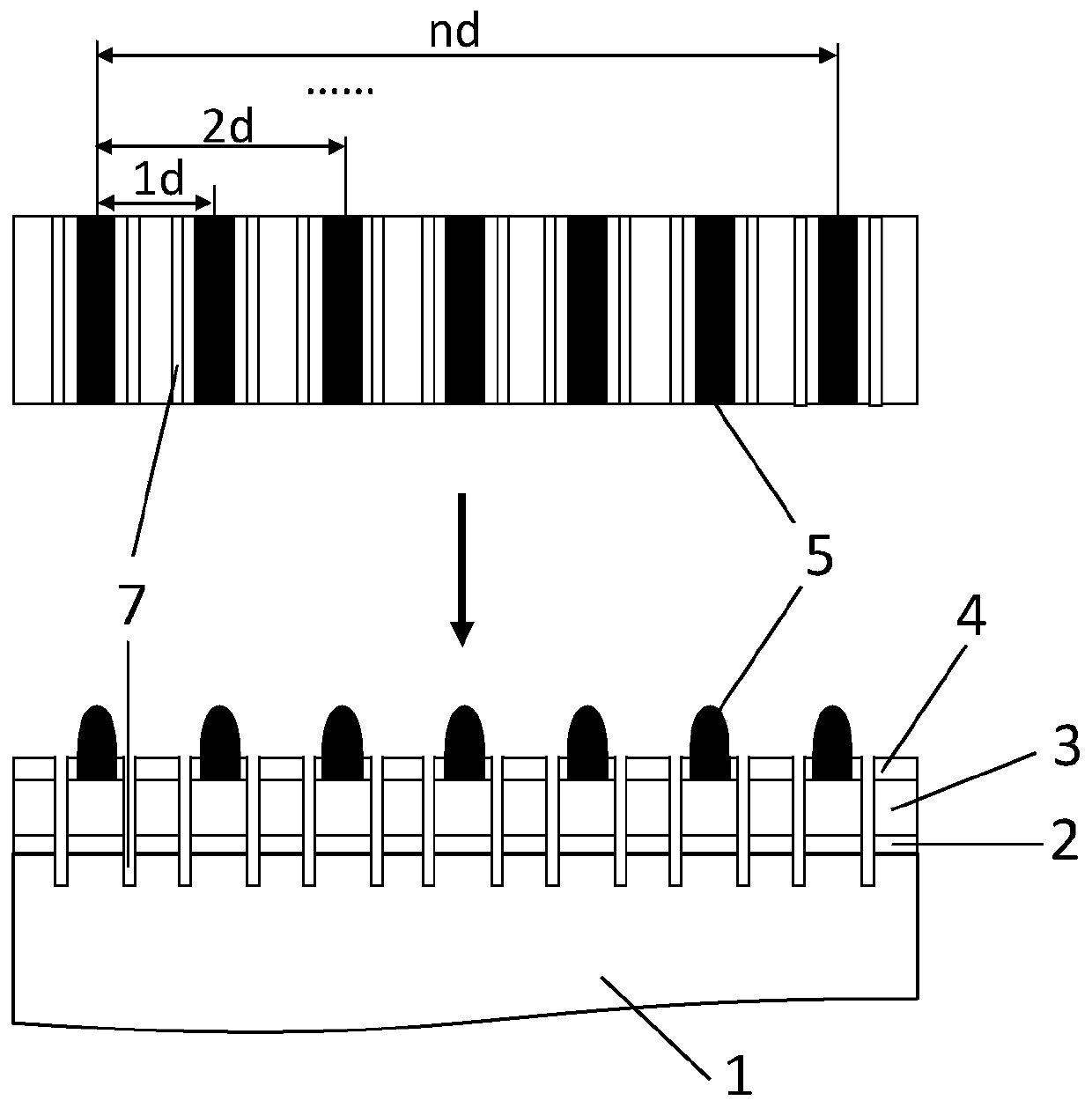
[0054] (1) Along the direction parallel to the sub-gate line on the battery sheet, groove the passivation contact structure next to both sides of the sub-gate line to form a groove structure; wherein, the groove structure extends longitudinally to the silicon the interior of the substrate;

[0055] (2) Along the direction parallel to the busbars on ...


PUM

PropertyMeasurementUnit
widthaaaaaaaaaa
widthaaaaaaaaaa
thicknessaaaaaaaaaa

Abstract

The invention relates to a method for testing the contact resistivity of a passivation contact structure, and the method comprises the steps: (1) carrying out the grooving on the passivation contact structure close to two sides of an auxiliary grid line along a direction, parallel to the auxiliary grid line, of a cell piece, and forming a groove structure, wherein the groove structure longitudinally extends into the silicon substrate; (2) cutting the area containing the groove structure along the direction parallel to the main grid line on the battery piece to obtain a test sample, wherein thetest sample does not contain a main grid line; (3) testing resistance values corresponding to different auxiliary grid line intervals on the test sample; (4) drawing a scatter diagram by taking the distance between the auxiliary grid lines as an abscissa and the resistance value corresponding to the distance between the auxiliary grid lines as an ordinate, and performing linear fitting to obtainthe slope and intercept of a linear function; and calculating the contact resistivity according to the slope and intercept of the linear function and a line transmission model.

Description

technical field [0001] The invention relates to the technical field of solar cells, in particular to a method for testing the contact resistivity of a passivation contact structure. Background technique [0002] Passivation contact structures, such as tunnel oxide layer / doped polysilicon layer, ultra-thin intrinsic amorphous silicon layer / heavily doped amorphous silicon layer, not only have excellent interface passivation performance, can significantly reduce metal contact recombination, but also have excellent Excellent contact performance, which facilitates the efficient transport of majority carriers. The excellent performance of the passivation contact structure has attracted extensive attention from research institutions and enterprises. Research institutions such as Fraunhofer in Germany and ISFH Institute of Solar Energy Systems have developed TOPCon batteries and POLO batteries for tunnel oxide / doped polysilicon layer structures. Enterprises such as China Lai, Tianh...

Claims


Application Information

Patent Timeline
Patent Type & Authority Applications(China)
IPC IPC(8): H01L21/66H01L31/0224
CPCH01L22/14H01L31/022425
Inventor 包杰马丽敏黄策乔振聪刘志锋陈嘉林建伟
Owner TAIZHOU ZHONGLAI PHOTOELECTRIC TECH CO LTD
Why Eureka
Try Eureka