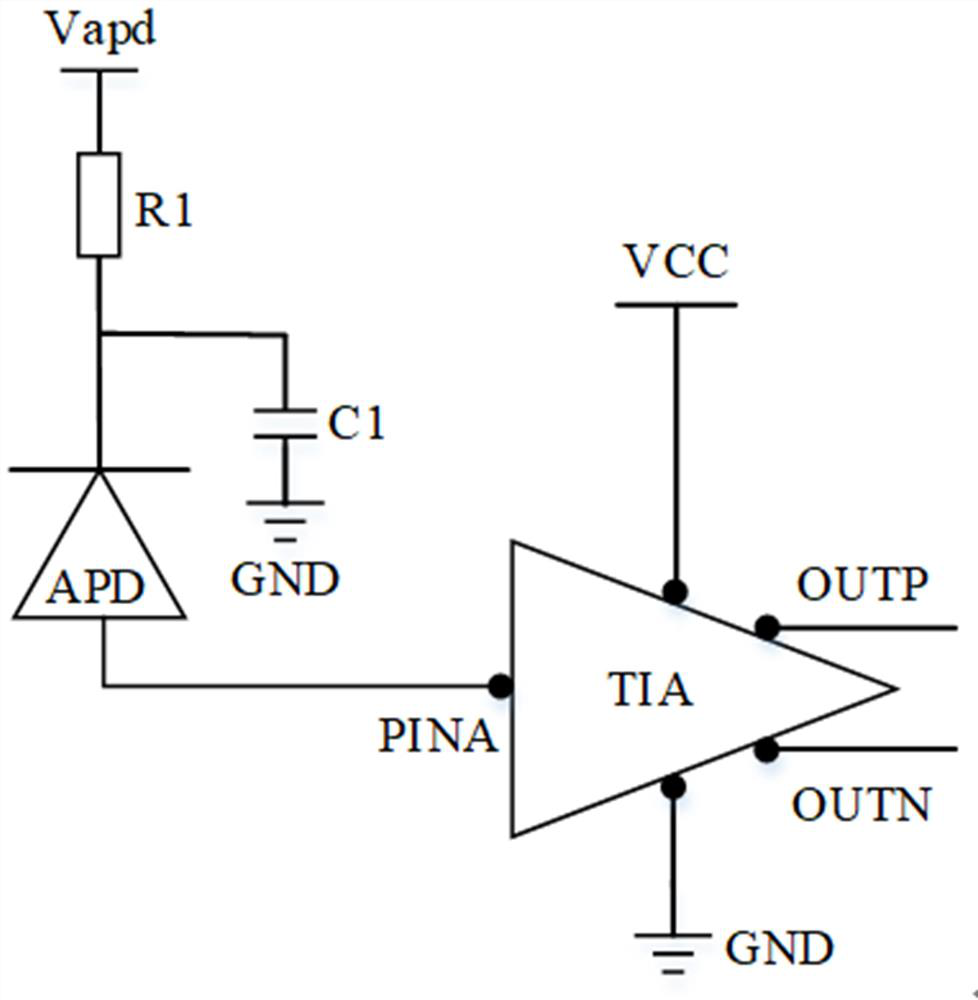
Transimpedance amplifier chip and light receiving module
A transimpedance amplifier and optical receiving technology, which is applied in the field of optical communication, can solve the problems of reducing the sensitivity performance of optical receivers, and achieve the effects of eliminating the space limitation of packaging and wiring, improving sensitivity, and simplifying packaging and wiring schemes
- Summary
- Abstract
- Description
- Claims
- Application Information
AI Technical Summary
Problems solved by technology
Method used
Image
Examples
Embodiment 1
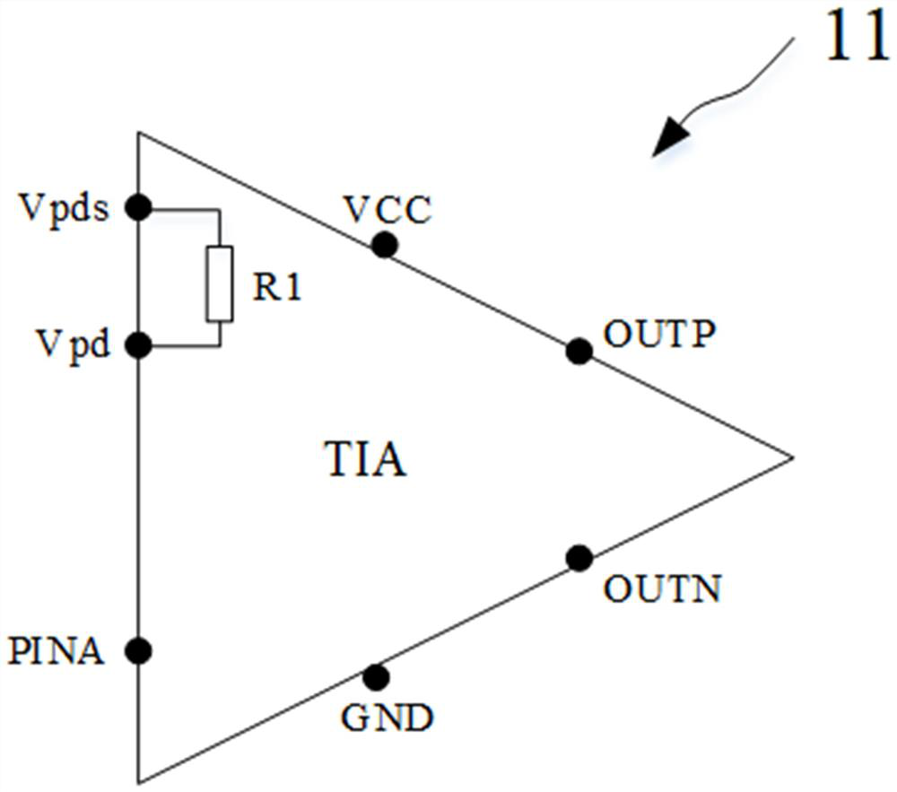
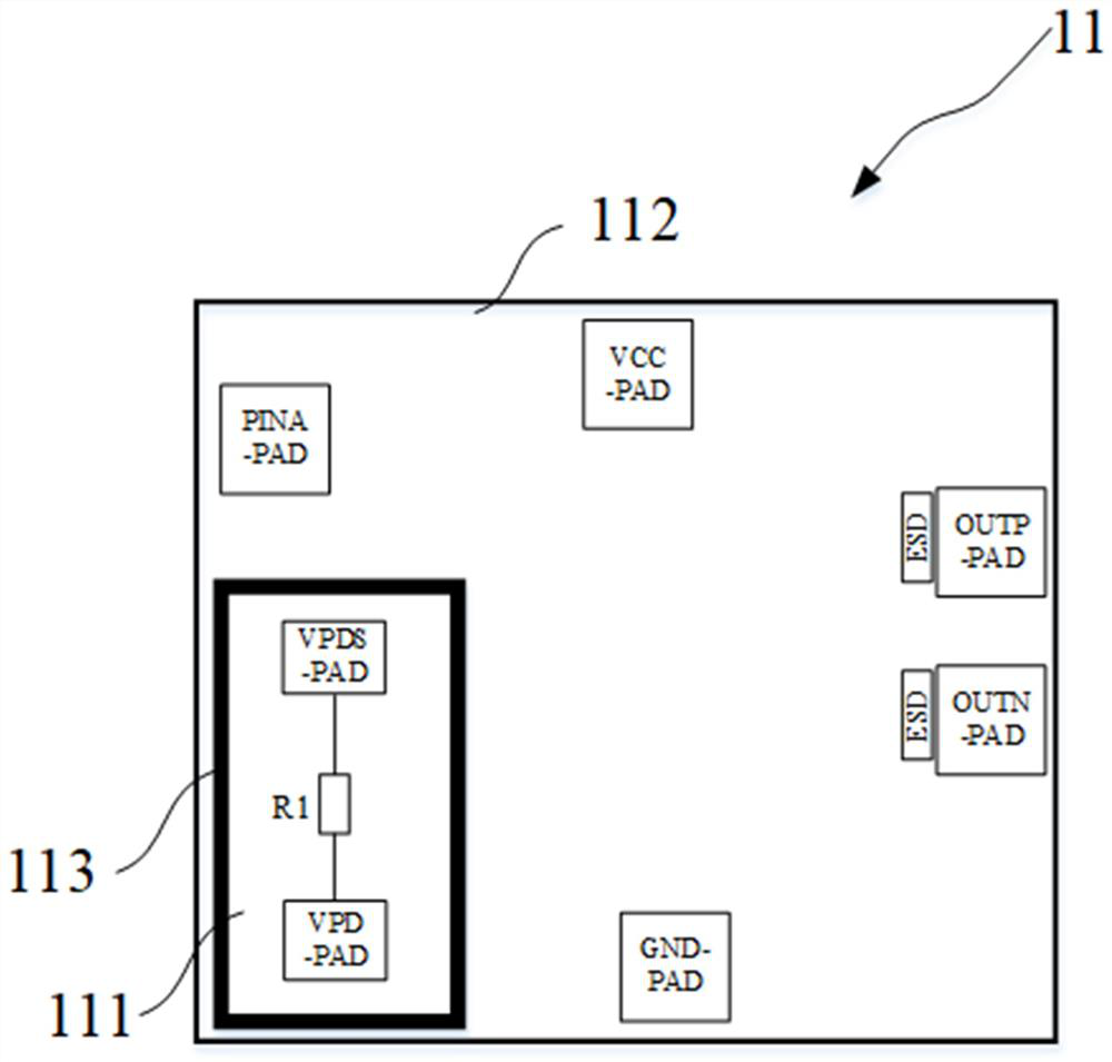
[0038] Such as Figure 2~Figure 4 As shown, the present embodiment provides a transimpedance amplifier chip 11 , in which the filter resistor R1 is integrated into the transimpedance amplifier chip 11 and corresponding pads are provided. The transimpedance amplifier chip 11 includes:
[0039] A filter resistor region 111 , a transimpedance amplifier device region 112 and a deep trench 113 are built in.
[0040] Such as image 3 and Figure 4 As shown, a filter resistor R1 is formed in the built-in filter resistor region 111 .
[0041]Specifically, the filter resistor R1 is formed on the substrate and is not electrically connected to the substrate (that is, an insulating material layer is provided between the filter resistor R1 and the substrate). As an example, the material of the filter resistor R1 includes Poly or Tin, wherein the withstand voltage of Poly can reach 200V, and any material with a withstand voltage greater than the voltage value of the bias voltage Vapd is...
Embodiment 2
[0054] Such as Figure 5 As shown, this embodiment provides a light receiving module 1, the light receiving module 1 includes:
[0055] The photodetector, filter capacitor C1 and transimpedance amplifier chip 11 packaged in the same package.
[0056] Such as Figure 5 As shown, the two ends of the photodetector are respectively connected to the photocurrent input terminal PINA of the transimpedance amplifier chip 1 and the first terminal Vpd of the filter resistor R1 in the transimpedance amplifier chip 1 through corresponding pads.
[0057] Specifically, as an example, the photodetector adopts a photodiode PD, the cathode of the photodiode PD is connected to the first terminal Vpd of the filter resistor R1, and the anode of the photodiode PD is connected to the light source of the transimpedance amplifier. Current input PINA. The photodiode PD is preferably an avalanche photodiode APD, and a larger current signal can be obtained through the photoelectric effect of the aval...
PUM
 Abstract
Description
Claims
Application Information
 - R&D
- Intellectual Property
- Life Sciences
- Materials
- Tech Scout
- Unparalleled Data Quality
- Higher Quality Content
- 60% Fewer Hallucinations
Browse by: Latest US Patents, China's latest patents, Technical Efficacy Thesaurus, Application Domain, Technology Topic, Popular Technical Reports.
© 2025 PatSnap. All rights reserved.Legal|Privacy policy|Modern Slavery Act Transparency Statement|Sitemap|About US| Contact US: help@patsnap.com


