Compositions, devices, and methods for organ sustained maintenance
A technology of isolated organs and containers, applied in the field of medical devices, to achieve the effect of prolonging the storage time
- Summary
- Abstract
- Description
- Claims
- Application Information
AI Technical Summary
Problems solved by technology
Method used
Image
Examples
Embodiment 1
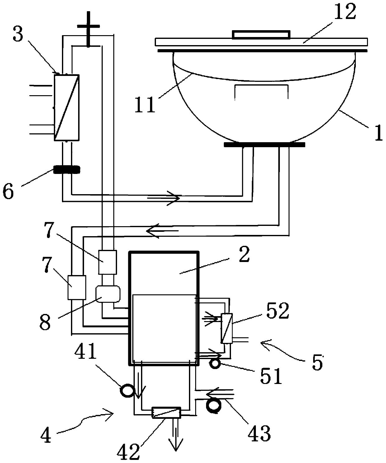
[1016] figure 1 It is a schematic structural diagram of the organ mechanical perfusion device in Example 1. In this embodiment, the organ mechanical perfusion device includes a container 1 , a pumping unit 2 , an oxygenator 3 and an ultrafiltration unit 4 . A holder 11 is arranged inside the container 1 , and a cover 12 is arranged on the top of the container 1 . The pumping unit 2 and the oxygenator 3 are arranged in series in the pipeline between the outlet and the inlet of the container 1, wherein the pumping unit 2 is used to drive the perfusate in the whole device to flow to form a continuous perfusion flow, oxygenation The device 3 is used for extracorporeal oxygenation and carbon dioxide discharge of the flowing perfusate, increasing the oxygen content of hemoglobin in the perfusate flowing back into the container 1 and the ultrafiltration effect on the loose R-state hemoglobin. The ultrafiltration unit 4 is connected with the perfusate bag in the pumping unit 2 and ...
Embodiment 2
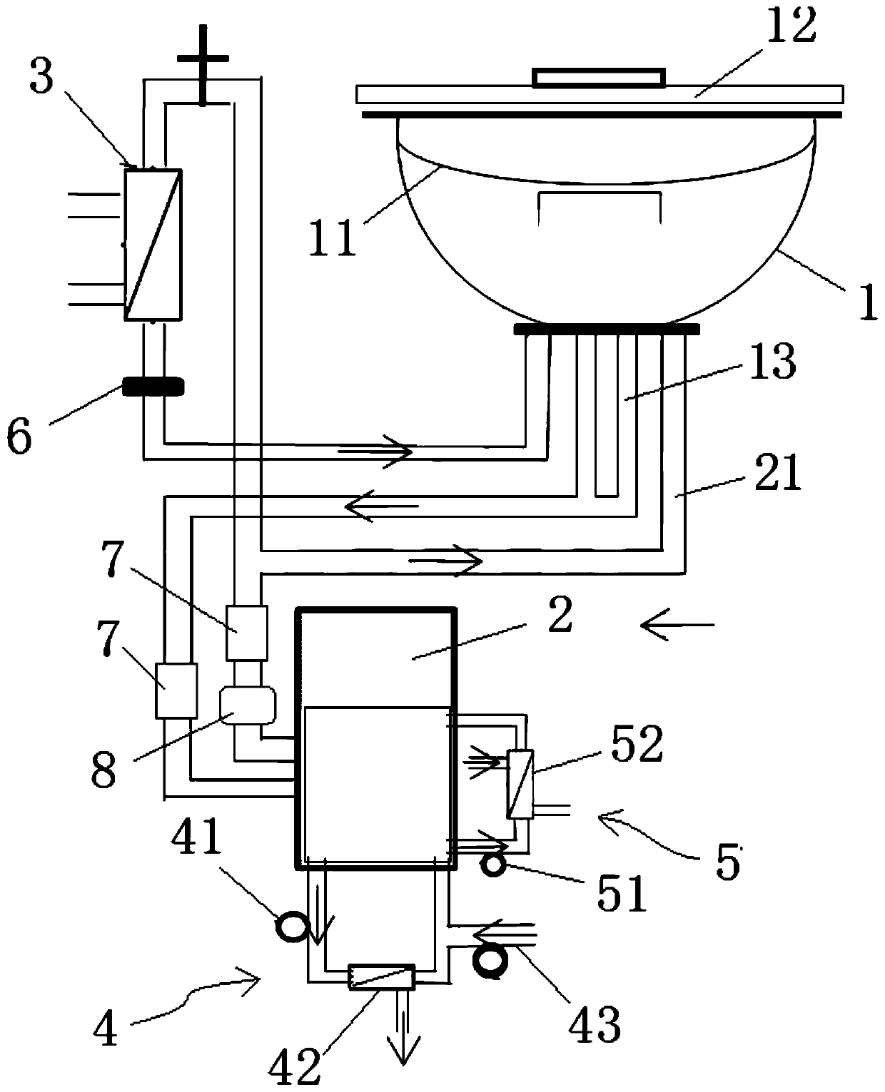
[1027] figure 2 It is a schematic structural diagram of the organ mechanical perfusion device in Example 2. The difference between the organ mechanical perfusion device in this embodiment and the organ mechanical perfusion device in Embodiment 1 is that there is also a perfusion organ return pipe 13 between the outlet of the container 1 and the inlet of the pumping unit 2, and the outlet of the pumping unit 2 A perfusion organ liquid inlet pipe 21 is also provided between the inlet of the container 1, thereby forming a double-pipeline perfusion structure for the organ. In this way, for the perfusion operation of some organs, such as the perfusion operation of the liver, the double-line perfusion with portal vein and aorta can be realized, thereby improving the perfusion application of the device to different organs, expanding the scope of use of the device, and improving its use. efficiency.
Embodiment 3
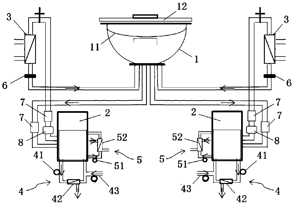
[1029] image 3 It is a schematic structural diagram of the organ mechanical perfusion device in Example 3. The difference between the organ mechanical perfusion device in this embodiment and the organ mechanical perfusion device in Embodiment 1 is that two sets of independent pumping units 2, oxygenators 3 and ultrafiltration units 4 are provided to form a double set of containers 1. Parallel perfusate circulation. In this way, a double perfusate circulation for the organs in the container can be formed, which can not only improve the efficiency and stability of the perfusion treatment of the organs, but also realize the setting of a separate circulation system such as pressure and flow to meet more complex requirements. Perfusion needs. Similarly, in other embodiments, the number of pumping units, oxygenators, and ultrafiltration units can also be adjusted according to the perfusion and preservation conditions of the organ, so as to meet the requirements of perfusion and p...
PUM
| Property | Measurement | Unit |
|---|---|---|
| Molecular weight | aaaaa | aaaaa |
Abstract
Description
Claims
Application Information
 - R&D
- Intellectual Property
- Life Sciences
- Materials
- Tech Scout
- Unparalleled Data Quality
- Higher Quality Content
- 60% Fewer Hallucinations
Browse by: Latest US Patents, China's latest patents, Technical Efficacy Thesaurus, Application Domain, Technology Topic, Popular Technical Reports.
© 2025 PatSnap. All rights reserved.Legal|Privacy policy|Modern Slavery Act Transparency Statement|Sitemap|About US| Contact US: help@patsnap.com


