
Preparation method of a photo-driven carbon nanotube helical fiber composite driver

A technology of fiber composite materials and carbon nanotubes, applied in the field of material science, can solve problems such as low resin content, impact on driving performance, and unrealized photo-induced actuation

Active Publication Date: 2022-02-18
HARBIN INST OF TECH
View PDF4 Cites 0 Cited by
  • Summary
  • Abstract
  • Description
  • Claims
  • Application Information

AI Technical Summary

Problems solved by technology

[0003] In order to solve the problems of slow response time, small driving force and single driving form of the existing carbon nanotube fiber driver, as well as the influence of the driving performance caused by the low resin content of the carbon nanotube helical fiber driving structure, and the photo-induced driving has not been realized, The invention provides a preparation method of a photoinduced driving carbon nanotube helical fiber composite driver

Method used


Image

  • Preparation method of a photo-driven carbon nanotube helical fiber composite driver
  • Preparation method of a photo-driven carbon nanotube helical fiber composite driver
  • Preparation method of a photo-driven carbon nanotube helical fiber composite driver

Examples


specific Embodiment approach 1

[0030] Specific Embodiment 1: This embodiment provides a method for preparing a carbon nanotube helical fiber composite driver driven by light, and the method is carried out according to the following steps:

[0031] Step 1, the preparation of carbon nanotube film:

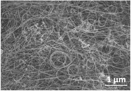
[0032]The method of chemical vapor deposition is used to prepare the carbon nanotube thin film. The specific steps are as follows: the catalyst ferrocene and the growth promoter sublimated sulfur are dissolved in the liquid carbon source xylene to obtain a mixed solution of the catalyst, the growth promoter and the carbon source , wherein: the preparation ratio of ferrocene, sublimated sulfur and xylene is to dissolve 0.1-40g of ferrocene powder and 0.002-1g of sublimated sulfur per 10-500mL of xylene; a precision injection pump (model LSP02-B, purchased From Baoding Lange Constant Current Pump Co., Ltd.), the mixed solution of catalyst, growth promoter and carbon source was injected into the preheating zone of a ...

specific Embodiment approach 2

[0042] Specific embodiment 2: The difference between this embodiment and specific embodiment 1 is that in step 1, the ferrocene and sublimed sulfur are dissolved in liquid carbon source xylene by ultrasonic means, and the ultrasonic time is 10-300min, and the ultrasonic power 10~200 kHz; the temperature of the preheating zone is 150~500°C, the temperature of the reaction zone is 900~1300°C; the H 2 / Ar carrier gas, H 2 The volume ratio of Ar and Ar is 1:1~4, and the carrier gas flow rate is 400~2000 mL / min.

specific Embodiment approach 3

[0043] Specific embodiment three: the difference between this embodiment and specific embodiment one is: in step one, H 2 / Ar carrier gas brings the carbon source, catalyst and growth promoter into the reaction zone of the tube furnace for reaction, specifically: cracking occurs first, and the cracked carbon atoms and carbon atom clusters are under the action of the iron catalyst cracked by ferrocene , grow into carbon nanotubes, and the carbon nanotubes produced by the reaction are quickly taken out of the growth area by the mixed flow of argon and hydrogen, and are evenly deposited in the product collection area to form a large-area carbon nanotube film.


PUM


Abstract

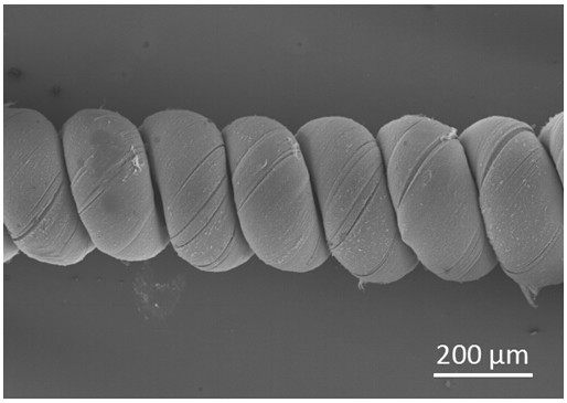
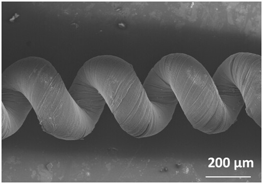
The invention discloses a method for preparing a photo-driven carbon nanotube helical fiber composite driver. The method includes the following steps: step 1, preparation of a carbon nanotube film; step 2, preparation of a carbon nanotube helical fiber; step 3. Configuring an epoxy resin curing system; Step 4: Pre-stretching the carbon nanotube helical fiber; Step 5: Preparation of a photo-driven carbon nanotube helical fiber composite driver. The carbon nanotube helical fiber composite material prepared by the present invention realizes the uniform infusion of epoxy resin in the carbon nanotube helical fiber, and the modulus of the epoxy resin can be regulated by adjusting the wavelength and power of near-infrared light, so that the carbon nanotube The driving performance such as the output force and response time of the helical fiber composite driver is regulated.

Description

technical field [0001] The invention belongs to the technical field of material science, and relates to a preparation method of a carbon nanotube helical fiber composite driver driven by light. Background technique [0002] With the continuous advancement of science and technology and the continuous development of bionics, human beings continue to develop robots and intelligent mechanical systems based on bionic structures. Artificial muscles, which are the key to driving robots and intelligent mechanical systems, have become the focus of research in the field of bionics. Carbon nanotube fibers are also used as artificial muscle materials due to their good high electrical conductivity and high thermal conductivity. Common carbon nanotube fibers are generally in the form of straight filaments, which show good application prospects in flexible and stretchable devices. They can be bent to a certain extent, and can be stretched with the help of organic substrates. However, duri...

Claims


Application Information

Patent Timeline
Patent Type & Authority Patents(China)
IPC IPC(8): C08L63/00C08K7/06D01F9/127
CPCC08K7/06D01F9/1276C08K2201/011
Inventor 彭庆宇徐亮亮赫晓东
Owner HARBIN INST OF TECH
Learn More