
A metal roof system

A technology for metal roofs and metal houses, which is applied to roofs, roof coverings, and roofs using flat/curved panels, etc., can solve the problems of increasing the cost of raw materials for main purlins, high labor intensity for operators, and low erection efficiency. Construction costs and steps, improving construction efficiency, easy processing and deformation effects

Active Publication Date: 2021-09-28
西安晴竣建筑装饰工程有限公司
View PDF20 Cites 0 Cited by
  • Summary
  • Abstract
  • Description
  • Claims
  • Application Information

AI Technical Summary

Problems solved by technology

The metal roof system is the outermost layer of the steel structure building. It is generally fixed directly to the main purlin and the secondary purlin of the building roof truss by screws. In the natural environment such as large temperature difference, strong wind, and heavy rain for a long time, the screw is prone to fall off and the Abnormal conditions such as looseness, water leakage, air leakage, and noise make it necessary to continuously repair the steel structure building, which affects the normal use and service life of the steel structure building
[0004] Moreover, the top of the roof truss of existing buildings generally needs to set up multiple secondary purlins on the main purlin, so as to ensure the strength of the building roof. If multiple secondary purlins are erected on the main purlin, the following disadvantages will occur: 1. The number of secondary purlins is large, and the erection period is long, which greatly increases the raw material cost and construction cost of the steel structure building; 2. When the secondary purlins are erected on the main purlins, operators need to install the roof bottom plate under the main purlins, and then install them on the main purlins. Rock wool layer, metal roof panels and other structures are erected above the purlins, which makes the erection of the metal roof system complicated, low in efficiency, high in cost, and high in labor intensity; 3. Multiple secondary purlins will generate serious loads on the main purlins pressure, which increases the raw material cost of the main purlin

Method used


Image

  • A metal roof system
  • A metal roof system
  • A metal roof system

Examples


Embodiment 1

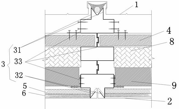
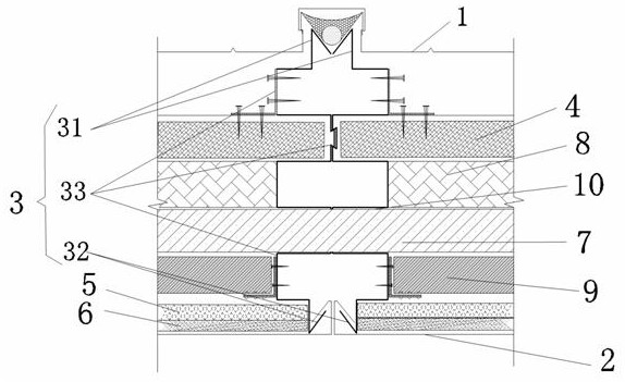
[0053] This example provides a metal roof system suitable for plane without curves, and the specific connection adopts the first connection structure; in this embodiment, please refer to figure 1 and figure 2 shown in which, figure 1 A schematic cross-sectional view showing the location of the main purlin; figure 2 It is a schematic cross-sectional view without showing the location of the main purlin. In this embodiment, the metal roof system includes a metal roof on the upper part of the main purlin and a roof bottom plate on the lower part of the main purlin. The metal roof is formed by sequentially connecting metal roof panels 1 of P blocks (P is an integer greater than or equal to 2). In the embodiment, after the adjacent metal roof panels 1 are in contact, weather-resistant adhesive is used to seal and connect the joints between the adjacent metal roof panels 1 and the following first connection structure, and finally the contact places are fastened by the aluminum-ma...

Embodiment 2

[0060] This embodiment is a further improvement on the basis of embodiment 1. The difference between this embodiment and embodiment 1 is that this embodiment is to further optimize the first connection structure in embodiment 1 to further improve the first connection structure. The supporting effect of a connection structure, the first connection structure is a plate-type or box-type structure, and the first connection structure includes an upper bite part, a lower fastening part, and a support part. In this embodiment, the first connection structure is preferably a plate structure.

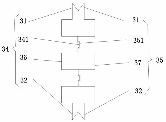
[0061] The first connecting structure of the present embodiment comprises the left panel purlin 34 and the right panel purlin 35, such as Figure 3a , Figure 3b , Figure 3c , Figure 3d As shown, among them, Figure 3a and Figure 3c It is a schematic diagram of the bite connection between the left panel purlin 34 and the right panel purlin 35 in the first connection structure; Figure 3b...

Embodiment 3

[0069] This example provides a metal roof system suitable for multi-curved structures, using the second connection structure; please refer to Figure 4 As shown, in this embodiment, please refer to Figure 4 As shown, the metal roof system includes the metal roof on the upper part of the main purlin and the roof bottom plate on the lower part of the main purlin. The metal roof is formed by sequentially connecting P blocks (P is an integer greater than or equal to 2) metal roof panels 1. In this embodiment After the adjacent metal roof panels 1 are in contact, weather-resistant adhesive is used to seal and connect the joints between the adjacent metal roof panels 1 and the second connection structure described below, and finally the contact places are fastened and connected by an aluminum-magnesium-manganese alloy buckle cover. The roof bottom plate is formed by sequentially connecting Q blocks (Q is an integer greater than or equal to 2) suspended floor plates 2 .

[0070] Th...


PUM


Abstract

The invention provides a metal roof system. The metal roof system of the invention includes a first connection structure and a second connection structure; the first connection structure is suitable for a flat non-curved metal roof system; the second connection structure is suitable for a multi-curved and special-shaped structure Metal roof system; the top of the first connection structure and the second connection structure are connected to the metal roof, and the bottom is connected to the roof floor; the first connection structure and the second connection structure are provided with a row of multiple through holes, and the through holes are along the It is set in the length direction, and the through holes form the penetration area through which the main purlin passes; it also includes a rock wool layer, which is located in the square area surrounded by the first connection structure or the second connection structure, the main purlin, the metal roof, and the roof bottom plate It also includes the glass wool layer and breathable membrane layer on the top of the roof bottom plate. The invention does not require the erection of the purlins, reduces the construction strength, simplifies the construction method, improves the construction efficiency and reduces the construction cost.

Description

technical field [0001] The invention relates to the technical field of roofing of buildings, in particular to a metal roofing system. The metal roofing system of the invention is suitable for the construction of flat, non-curved or multi-curved metal houses. Background technique [0002] Steel structure buildings are composed of steel materials and are one of the common types of building structures at present. At present, steel structure buildings are composed of beams, steel columns, main purlins, secondary purlins and other components to form a building roof truss, and then a metal roof system is erected on the building roof truss to form a complete building, such as the current large factories, venues, famous buildings things etc. [0003] Metal roofing system is used as the plate of steel structure building, and it is often used in construction projects. Metal roofing system is used to protect steel structure buildings from waterproof and sun protection. The metal roof...

Claims


Application Information

Patent Timeline
Patent Type & Authority Patents(China)
IPC IPC(8): E04D11/00E04D3/36E04D3/362E04G21/32
CPCE04D3/3607E04D3/3608E04D3/362E04D11/00E04D11/005E04G21/3266
Inventor 雷勇高文涛
Owner 西安晴竣建筑装饰工程有限公司
Learn More