
Plasma flame catalytic activation coal powder burner for cement plant

A pulverized coal burner and catalytic activation technology, which is applied to burners, burners, plasma and other directions of burning powder fuel, can solve the problem of unsatisfactory pulverized coal burnout rate in time, stable operation of pollutant kiln system, and combustion performance. The problem of poor reaction activity, etc., can achieve the effect of strong adaptability to coal quality fluctuation, improving combustion efficiency and timely burning rate, and facilitating improvement and transformation.

Pending Publication Date: 2020-07-14
长沙紫宸科技开发有限公司
View PDF0 Cites 0 Cited by
  • Summary
  • Abstract
  • Description
  • Claims
  • Application Information

AI Technical Summary

Problems solved by technology

[0002] As we all know, cement production is an industry with high energy consumption and high pollution, and my country is the largest cement production country in the world. There are more than 1,700 dry-process cement production lines currently in operation. The advanced pulverized coal burners commonly used are generally 3 For pulverized coal burners with channel to channel 6, due to the source of coal quality or economic cost, the coal used by cement enterprises currently has poor combustion performance and reactivity, and the physical function bottleneck of existing advanced pulverized coal burners Restrictions lead to unsatisfactory timely burnout rate of pulverized coal, high coal consumption, pollutants produced by non-timely combustion of pulverized coal and side effects on the stable operation of the kiln system.
In order to improve the timely burnout rate of pulverized coal, some cement plants have to use oxygen-increasing devices to implement oxygen-increased combustion in order to improve the reactivity and timely burnout rate of pulverized coal. Equipment investment, oxygen consumption and increased energy consumption, low efficiency

Method used


Image

  • Plasma flame catalytic activation coal powder burner for cement plant
  • Plasma flame catalytic activation coal powder burner for cement plant
  • Plasma flame catalytic activation coal powder burner for cement plant

Examples


Embodiment 2

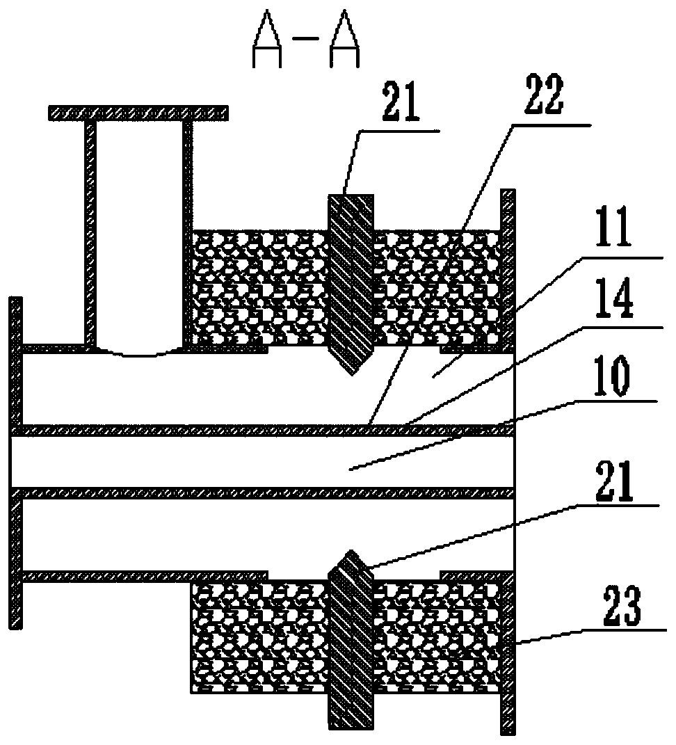
[0031] refer to Figure 3-5 , the discharge part 21 of the plasma flame catalytic device 2 described in this embodiment is fixed on the end 15 of the internal air duct of the burner through the insulating part 23; the rear end of the insulating part 23 is also provided with a magnetic control part 25, and the magnetic Control part 25 is made of electromagnetic coil, is installed in insulation part 23 rear parts.

[0032] All the other are the same as embodiment 1

Embodiment 3

[0034] refer to Figure 6-7 , the discharge part 21 of the plasma flame catalytic device 2 described in this embodiment is respectively fixed on the wall 14 of the inner air duct of the burner and the end part 15 of the inner air duct through the insulating member 23 .

[0035] All the other are the same as embodiment 1

Embodiment 4

[0037] refer to Figure 8-10 , the plasma flame catalytic device 1 of the present embodiment is arranged at the exit 16 of the internal air duct, the discharge part 21 of the plasma flame catalytic device 2 is a ring electrode, and the conductive part 22 is a ring electrode, and the discharge part 21 passes through The insulating part 23 is connected to the conductive part 22 , and the power supply device is connected to the discharge part 21 and the conductive part 22 through the cable provided in the central air duct 10 .

[0038] All the other are the same as embodiment 1


PUM


Abstract

The invention discloses a plasma flame catalytic activation coal powder burner for a cement plant. The burner comprises a multi-channel coal spraying pipe and a plasma flame catalytic device, whereinthe multi-channel coal spraying pipe is at least provided with an inner air duct, a coal powder channel and an outer air duct, and the plasma flame catalytic device is arranged in the inner air duct.The plasma flame generated by the plasma flame catalytic device arranged in the inner air duct (cyclone air duct) realizes catalytic activation of coal powder in a mode of outwards rotating, extrudingand rubbing the coal powder from the coal powder channel outside an outlet of the cyclone air duct, so that two-phase fuel is formed, a temperature of the coal powder is improved, the coal powder iscatalyzed and activated, and the combustion efficiency of the coal powder and the burn-out rate of inferior coal powder are improved.

Description

technical field [0001] The invention relates to a pulverized coal burner, in particular to a pulverized coal burner for plasma flame catalytic activation in a cement plant. Background technique [0002] As we all know, cement production is an industry with high energy consumption and high pollution, and my country is the largest cement production country in the world. There are more than 1,700 dry-process cement production lines currently in operation. The advanced pulverized coal burners commonly used are generally 3 For pulverized coal burners with channel to channel 6, due to the source of coal quality or economic cost, the coal used by cement enterprises currently has poor combustion performance and reactivity, and the physical function bottleneck of existing advanced pulverized coal burners Restrictions lead to unsatisfactory timely burnout rate of pulverized coal, high coal consumption, pollutants produced by non-timely combustion of pulverized coal and side effects on t...

Claims


Application Information

Patent Timeline
Patent Type & Authority Applications(China)
IPC IPC(8): F27D99/00F23D1/02F23Q3/00H05H1/48F23K3/02
CPCF23D1/02F23K3/02F23Q3/006F27D99/0033F27D2099/0031F27D2099/005H05H1/48
Inventor 尹小林余智英赵海洋刘婷肖姗姗皮静
Owner 长沙紫宸科技开发有限公司
Learn More