Metal flat tube supporting body, battery/electrolytic cell and battery stack structure

A support body and electrolytic cell technology, applied in the field of battery stack structure and metal flat tube support body, can solve problems such as poor sealing performance, and achieve the effects of preventing gas leakage, reducing manufacturing costs, and preventing gas leakage

Active Publication Date: 2020-07-14
XI AN JIAOTONG UNIV
View PDF8 Cites 0 Cited by
  • Summary
  • Abstract
  • Description
  • Claims
  • Application Information

AI Technical Summary

Problems solved by technology

[0007] However, metal-supported solid oxide fuel cells are mainly flat-plate type, and the sealing problem needs to be solved.

Method used


Image

  • Metal flat tube supporting body, battery/electrolytic cell and battery stack structure
  • Metal flat tube supporting body, battery/electrolytic cell and battery stack structure
  • Metal flat tube supporting body, battery/electrolytic cell and battery stack structure

Examples


Embodiment 1

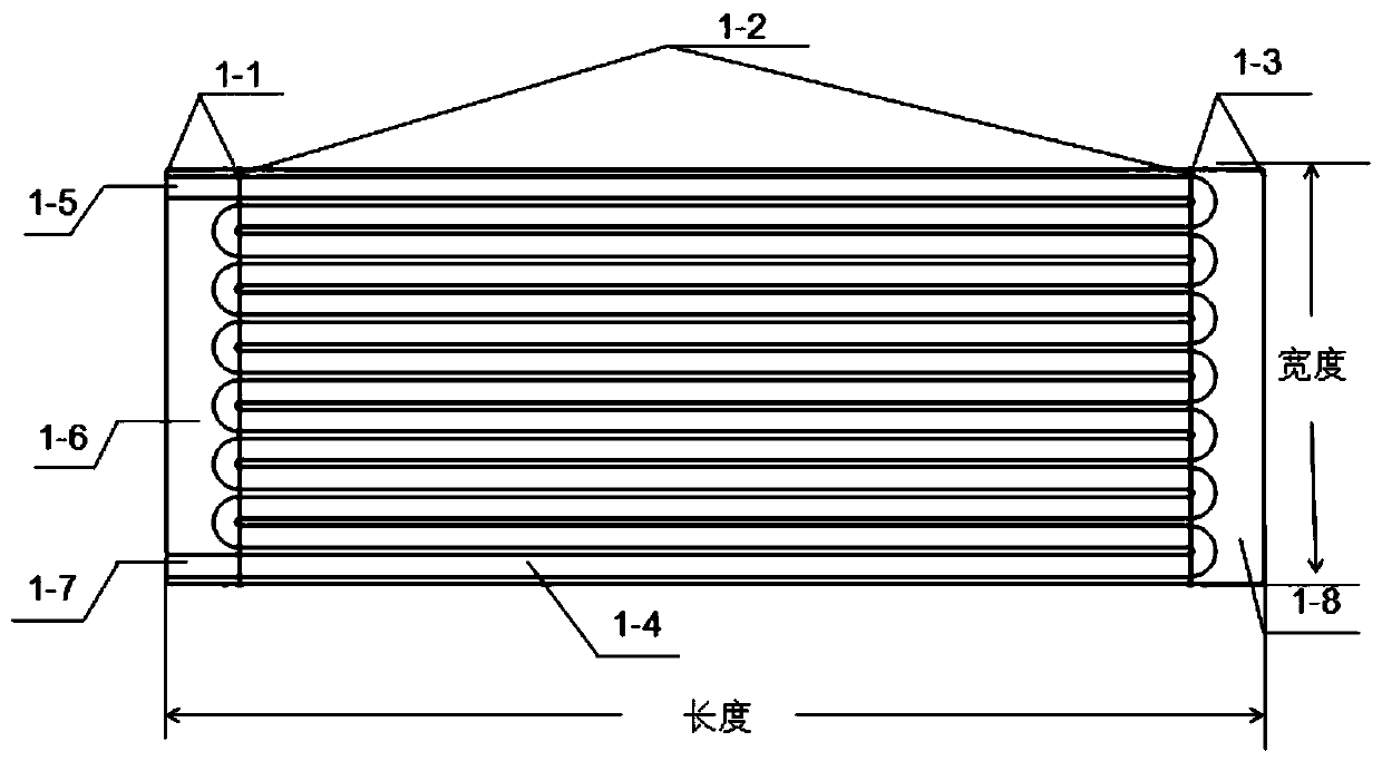
[0078] see figure 1 As shown, in this embodiment, iron-nickel alloy is used as the metal flat tube support body material, and the metal flat tube support body is formed by powder metallurgy sintering. : 15cm * 5cm, the middle section of the flat tube is porous, the porosity is 30%, the two ends are dense, and the inside has a serpentine gas flow channel, wherein, 1 cm of the blind hole end of the flat tube (that is, the closed end in the present invention) is a dense area , the 2cm at the end of the opening is a dense area, and the middle 12cm is a porous structure. The Ni / GDC anode was prepared by atmospheric plasma spraying on the porous structure of the metal support, covering the porous structure, the ScSZ electrolyte was prepared by atmospheric plasma spraying, the anode was completely wrapped, and the LSCF cathode was prepared on the electrolyte by atmospheric plasma spraying to complete the preparation of the single cell.

Embodiment 2

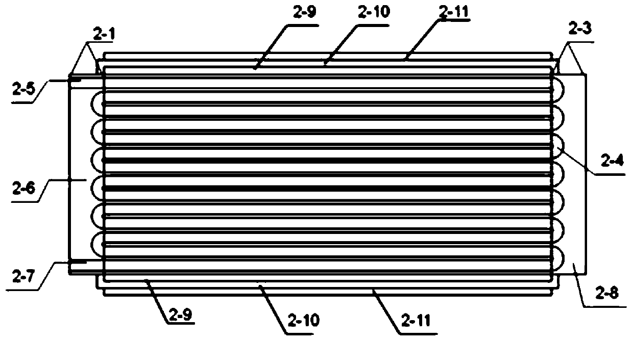
[0080] In this embodiment, pure chromium is used as the metal flat tube support material, and the metal flat tube support is prepared by powder metallurgy. The thickness of the flat tube is 1.2 cm, and the length and width of the upper and lower plane areas are 6 cm and 24 cm respectively. 15%, both ends are dense, and there is a gas flow channel inside the flat tube. Among them, the 1cm of the blind hole end of the flat tube is a dense area, and the 3cm of the open section is a dense area. The middle 20cm is a porous structure, and the sprayed Ni / GDC cathode wraps the middle porous support body, spray BZCY electrolyte to wrap the cathode and all exposed porous metal supports, screen-print LSM anodes on the two planes of the flat tube, and prepare an electrolytic cell after sintering. The prepared electrolytic cell exhibits a high hydrogen production rate.

Embodiment 3

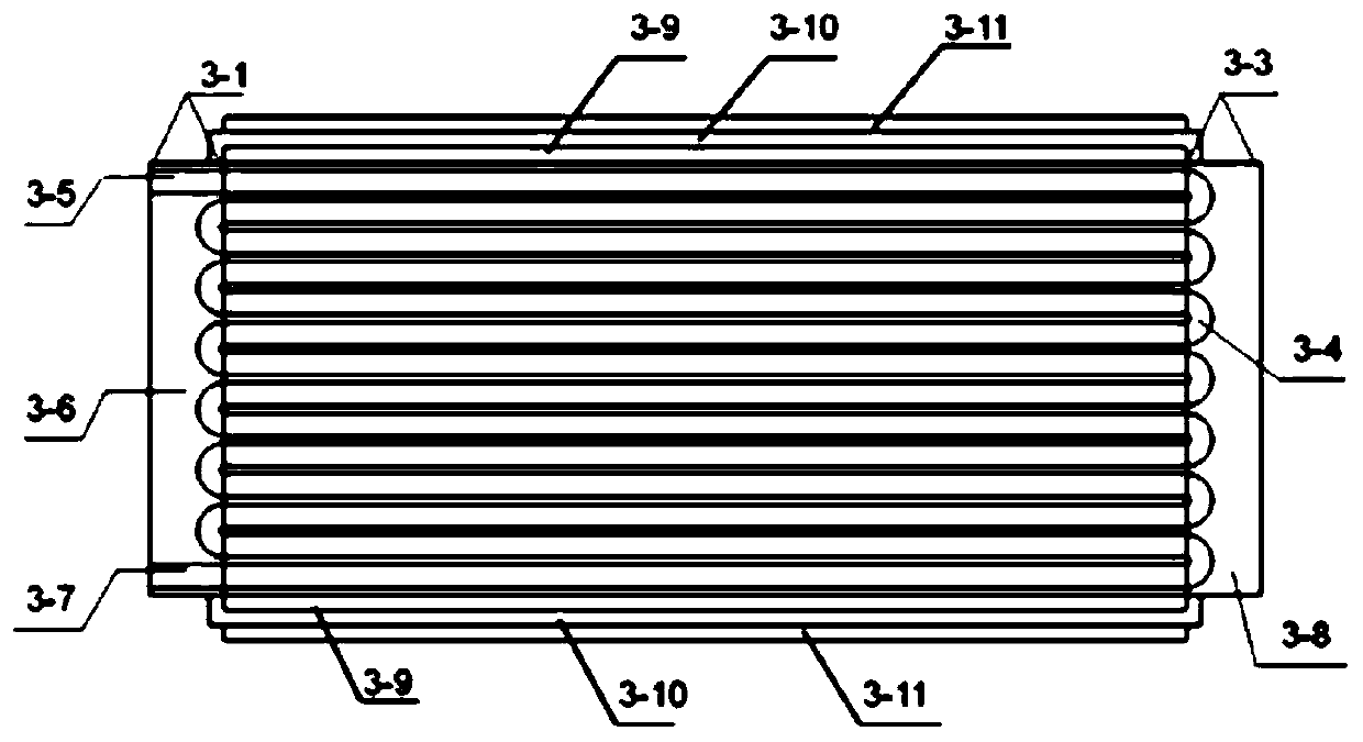
[0082] In this embodiment, iron-nickel alloy is used as the metal flat tube support body material, and the metal flat tube support body is formed by powder metallurgy sintering. A flat tube metal support body, wherein the 1 cm at both ends is a dense area, and the middle 28 cm is a porous structure with a porosity of 40%. The Ni / GDC anode was prepared by atmospheric plasma spraying on the porous structure of the metal support, covering the porous structure, the ScSZ electrolyte was prepared by vacuum plasma spraying, and the anode was completely wrapped, and the LSCF cathode was prepared by atmospheric plasma spraying on the electrolyte, and two porous metal sheets were Contact the cathodes on both sides of the flat tube through the elastic force to derive the current on the cathode side to complete the preparation of the single cell. Single cell expresses good voltage and power output.


PUM

PropertyMeasurementUnit
Thicknessaaaaaaaaaa
Thicknessaaaaaaaaaa
Thicknessaaaaaaaaaa

Abstract

The invention provides a metal flat tube supporting body, a battery/electrolytic cell and a battery stack structure. The metal flat pipe supporting body structure comprises a closed end, a porous structure, a fuel gas flow channel and an open end. The closed end and the open end are respectively positioned at two ends of the porous structure; the fuel gas flow channel is arranged in the porous structure and is used for circulating fuel gas; the closed end is of a compact structure and is used for sealing the first end of the fuel gas flow channel. According to the structure provided by the invention, the closed end and the open end are in contact with the electrolyte layer, so the purpose of self-sealing is achieved, and the sealing problem existing in the metal-supported solid oxide fuelcell is effectively solved.

Description

technical field [0001] The invention relates to the field of energy technology, in particular to a metal flat tube support body, a battery / electrolytic cell, and a battery stack structure. Background technique [0002] Solid oxide fuel cell (Solid oxide fuel cell abbreviated as SOFC) is a solid-state power generation device with high power generation efficiency, no noise and no pollution when working, and directly converts the chemical energy of the fuel into electrical energy without burning. The functional layer of a solid oxide fuel cell mainly includes three functional layers: an anode, an electrolyte, and a cathode. [0003] Currently, there are two basic structures of the SOFC structure, the tube type and the planar type. The biggest difference between the two lies in whether the direction of current collection and conduction is perpendicular to the direction of the electrolyte film or parallel to the direction of the electrolyte film. The advantages of flat-plate fu...

Claims


Application Information

Patent Timeline
IPC IPC(8): H01M8/00H01M8/0271H01M8/0286H01M8/04089H01M8/12H01M8/1231H01M8/243H01M8/2457C25B1/04C25B9/02
CPCC25B1/04C25B9/63H01M8/004H01M8/0271H01M8/0286H01M8/04201H01M8/12H01M8/243H01M2008/1293H01M8/1231H01M8/2457Y02E60/36Y02E60/50
Inventor 李成新康思远李甲鸿李长久张山林
Owner XI AN JIAOTONG UNIV
Why Eureka
Try Eureka