
Robot joint information acquisition method

A technology of robot joint and acquisition method, applied in the field of robot joint information acquisition, can solve the problems affecting the control performance of the robot and the poor quality of the joint acceleration signal, and achieve the effects of various layout methods, reasonable structure design, and convenient performance.

Inactive Publication Date: 2020-07-17
HARBIN UNIV OF SCI & TECH
View PDF7 Cites 1 Cited by
  • Summary
  • Abstract
  • Description
  • Claims
  • Application Information

AI Technical Summary

Problems solved by technology

[0003] The present invention is to solve the problem that the poor quality of the existing robot joint speed and joint acceleration signals affects the control performance of the robot, and provides a method for acquiring robot joint information

Method used


Image

  • Robot joint information acquisition method
  • Robot joint information acquisition method
  • Robot joint information acquisition method

Examples


Embodiment Construction

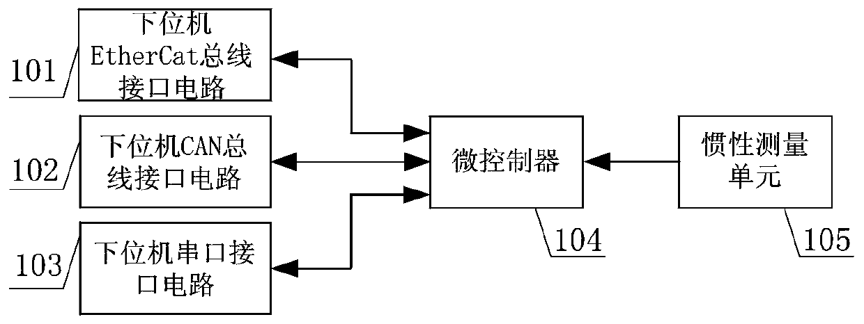
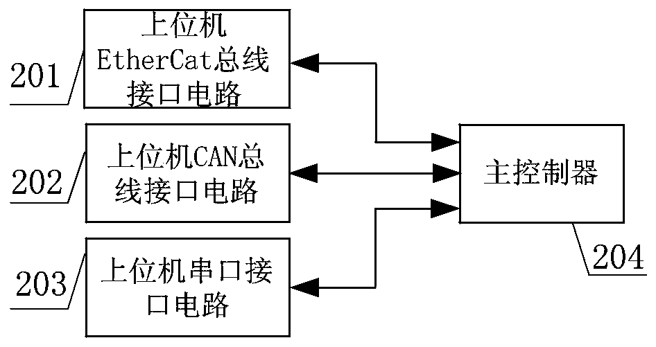
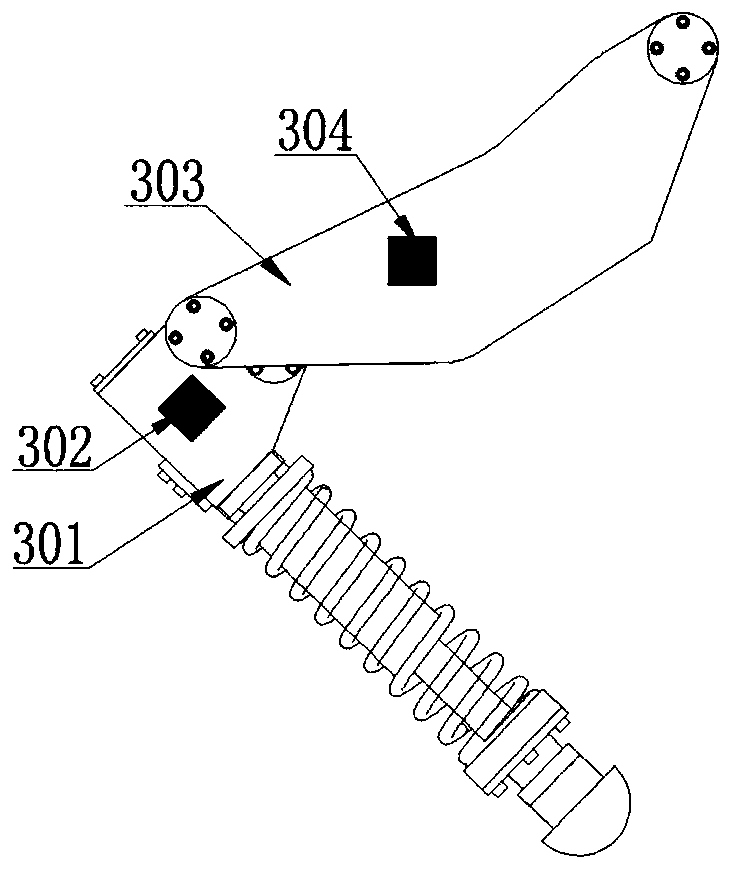
[0012] Combine below figure 1 , figure 2 and image 3 Describe this embodiment, a kind of robot joint information acquisition method described in this embodiment, it comprises lower computer EtherCAT bus interface circuit (101), lower computer CAN bus interface circuit (102), lower computer serial port interface circuit (103), Microcontroller (104), inertial measurement unit (105), upper computer EtherCAT bus interface circuit (201), upper computer CAN bus interface circuit (202), upper computer serial port interface circuit (203) and controller (204), inertial The measurement unit (105) transmits the triaxial angular velocity and triaxial acceleration information in the Cartesian coordinate system to the microcontroller (104), and the microcontroller (104) outputs the triaxial angular velocity and triaxial acceleration information according to the inertial measurement unit (105). The acceleration information calculates the three-axis angle information of the inertial coord...


PUM


Abstract

The invention provides a robot joint information acquisition method, belongs to the field of robots, and mainly solves the problem that the control performance of a robot is influenced due to poor joint speed and joint acceleration signal quality of the existing robot. According to the robot joint information acquisition method, joint displacement, joint speed and joint acceleration information are obtained through the angular speed and acceleration information output by an inertia measurement unit, meanwhile, under the condition that the joint torque is known, the current load mass of a driver can be estimated in real time, and reliable state information is provided for driver control. The method is reasonable in structural design, small in size, diversified in sensor arrangement mode andcapable of improving the performance of the robot conveniently.

Description

Technical field: [0001] The invention relates to a method for acquiring robot joint information, which belongs to the field of robots. Background technique: [0002] Robot joint displacement, joint velocity and joint acceleration play an important role in robot inverse dynamics calculation, state estimation and joint driver control. The joint displacement of the existing robot is obtained through the displacement sensor on the driver, and the joint velocity and joint acceleration information is obtained through the primary and secondary differential of the displacement sensor. Since the signal often produces signal noise during the differentiation process, which reduces the quality of the joint velocity and acceleration signals, although the signal quality can be improved through the filter, but the introduction of the filter also causes the phase of the differentiated signal to lag. It brings certain challenges to robot control. Invention content: [0003] The invention...

Claims


Application Information

Patent Timeline
IPC IPC(8): B25J9/16
CPCB25J9/1602B25J9/1694
Inventor 孙桂涛司俊山邵璇
Owner HARBIN UNIV OF SCI & TECH
Learn More