
A rapid test method and system for potential induction decay of solar cells

A solar cell and potential sensing technology, which is applied in the monitoring of photovoltaic systems, electrical components, photovoltaic power generation, etc., can solve the problem of inability to accurately obtain the potential induction attenuation performance of solar cells, difficult to meet rapid evaluation, and cannot be used to evaluate component packaging materials. performance issues

Active Publication Date: 2021-09-21
杭州晶宝新能源科技有限公司
View PDF4 Cites 0 Cited by
  • Summary
  • Abstract
  • Description
  • Claims
  • Application Information

AI Technical Summary

Problems solved by technology

There is already a corresponding method in the industry to test the potential-induced attenuation performance of solar cell packaging components. The applied voltage is 1000 volts, and the test takes more than 96 hours. However, the test time is very long and it is difficult to meet the requirements of rapid evaluation.
In addition, there are also related patents. For example, the patent document with the application number 201611214527. It is used to evaluate the performance of the component packaging material; moreover, it can only feed back the information of the local position of the solar cell through the discharge of the tip of the metal probe, and cannot accurately obtain the overall potential induced attenuation performance of the solar cell

Method used


Image

  • A rapid test method and system for potential induction decay of solar cells
  • A rapid test method and system for potential induction decay of solar cells
  • A rapid test method and system for potential induction decay of solar cells

Examples


Embodiment 1

[0041] The potential induction decay rapid test method of the solar cell and packaging material of the present embodiment includes:

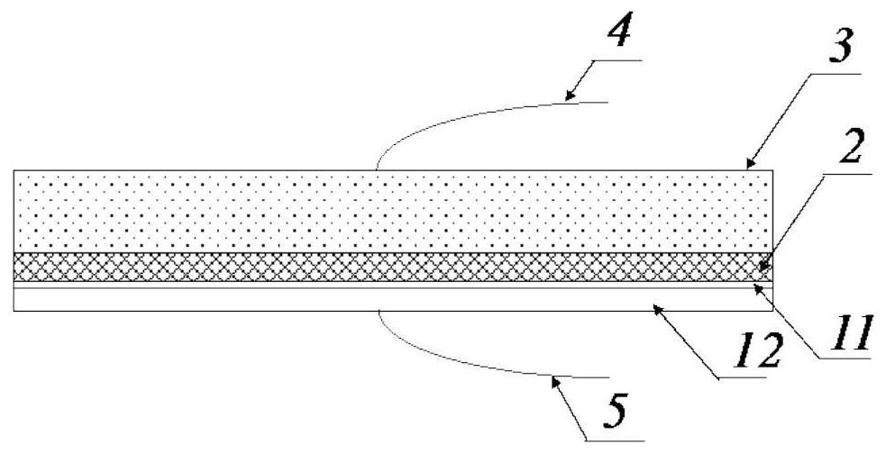
[0042] Such as figure 1 As shown, the solar cell, the encapsulating polymer material 2, such as ethylene-vinyl acetate copolymer (EVA) film, polyolefin elastomer film (POE), etc., and the encapsulating glass layer 3 are stacked sequentially from bottom to top to form a stack .

[0043]The two planar electrodes are closely combined with the upper and lower surfaces of the stack, the upper electrode 4 is connected to the positive pole of the DC high voltage power supply, and the lower electrode 5 is connected to the negative pole of the DC high voltage power supply. Wherein, the planar electrode is a planar metal electrode, preferably made of aluminum.

[0044] A voltage of 10 kV was applied between the two electrodes, the direction of the electric field was directed from the glass to the front surface of the solar cell, and the above stack was ...

Embodiment 2

[0047] The potential induction decay rapid test method of the solar cell and packaging material of the present embodiment includes:

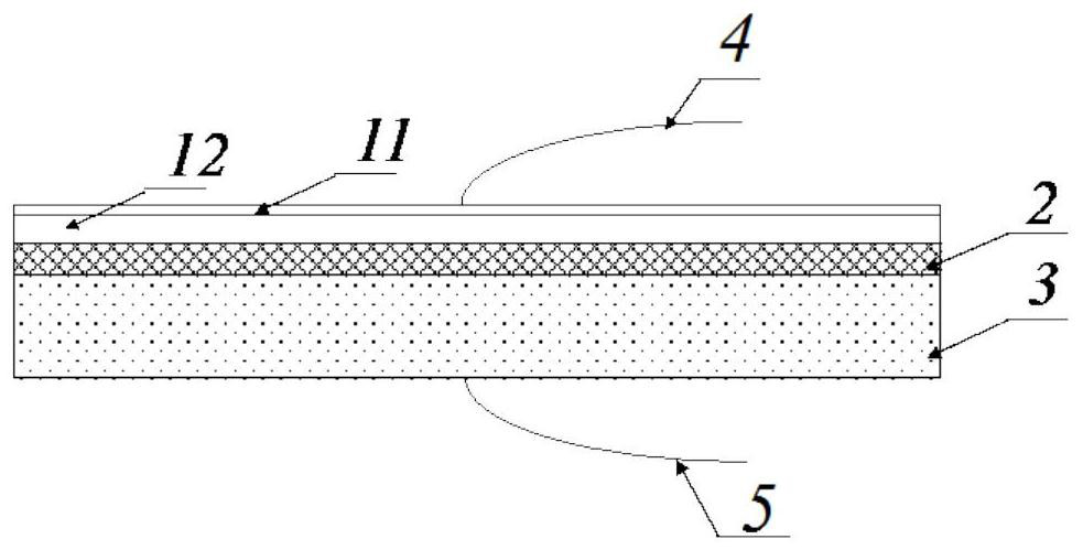
[0048] Such as image 3 As shown, the solar cell, the encapsulating polymer material 2 , the encapsulating glass or the back plate 3 are stacked sequentially from top to bottom to form a stack.

[0049] The two planar electrodes are closely combined with the upper and lower surfaces of the stack, the upper electrode 4 is connected to the negative pole of the DC high voltage power supply, and the lower electrode 5 is connected to the positive pole of the DC high voltage power supply. Wherein, the planar electrode is a planar metal electrode, preferably made of aluminum.

[0050] A voltage of 5 kV was applied between the two electrodes, and the above stack was kept at 60°C for 24 hours. After the process is over, the direct current high voltage is removed, the stack is cooled, and the solar cells are taken out and tested for electrical performan...

Embodiment 3

[0054] The potential induction decay rapid test method of the solar cell module of the present embodiment includes:

[0055] Such as Figure 4 As shown, the two planar electrodes are closely combined with the upper and lower surfaces of the solar cell module, the upper electrode 4 is connected to the positive pole of the DC high-voltage power supply, and the lower electrode 5 is connected to the output terminal of the module with a wire, and the above output terminal is connected to the lower half of the solar cell. For example, for a conventional p-type solar cell, the output end of which is the positive pole of the component, and the lower electrode 5 is then connected to the negative pole of the DC high-voltage power supply. Wherein, the planar electrode is a planar metal electrode, preferably made of aluminum.

[0056] A voltage of 15kV was applied between the two electrodes, and the direction of the electric field was directed from the upper surface glass layer to the so...


PUM


Abstract

The invention relates to a rapid test method for potential-induced attenuation of solar cells, comprising the following steps: S1, stacking packaging materials and solar cells to form a stack; S2, placing the stack in an environment with a preset temperature not greater than 120°C , and attach the two surfaces of the stack to the two planar electrodes respectively; S3, apply a forward or reverse DC voltage between the two electrodes, so that the direction of the electric field is directed from the glass layer of the encapsulation material to the solar cell; The applied DC voltage is 1-20 kV, and the holding time of the applied voltage is less than 96 hours; S4, after the applied DC voltage is released, the laminate is cooled to room temperature, and the solar cell is taken out from the laminate and tested for its electrical properties, to Obtain the potential-induced attenuation characteristics of solar cells and packaging materials. The invention applies a high voltage to the solar cell and the glass layer of the encapsulation material to generate a very strong electric field intensity between the two to drive the directional migration of sodium ions in the glass, thereby shortening the test time.

Description

technical field [0001] The invention belongs to the technical field of solar battery testing, and in particular relates to a method and system for quickly testing potential induction decay of solar batteries. Background technique [0002] In a photovoltaic power station, photovoltaic modules usually need to be connected in series to achieve a system voltage of about 1000-1500 volts. In order to prevent the risk of electric shock and inhibit the electrochemical corrosion of the module frame, the module frame is usually grounded, so that a potential difference of about 1 kV is formed between the battery and the module frame in the photovoltaic module. Under the action of this potential difference, the power generation performance of solar modules will drop significantly, which is called potential induced attenuation. Studies have found that this attenuation is mainly due to the sodium ions contained in the glass as the packaging material being driven by the above potential, p...

Claims


Application Information

Patent Timeline
Patent Type & Authority Patents(China)
IPC IPC(8): H02S50/10
CPCH02S50/10Y02E10/50
Inventor 李晓强陈鹏
Owner 杭州晶宝新能源科技有限公司
Learn More