Energy-saving carrier gas stripping system and stripping process

An energy-saving, carrier gas technology, used in fractionation, distillation separation, vacuum distillation, etc., can solve the problems of poor fractionation accuracy, high energy consumption, and high separation temperature, and achieve small equipment footprint, low separation temperature, and high separation accuracy. Effect

Pending Publication Date: 2020-07-28
陕西聚能新创煤化科技有限公司
View PDF6 Cites 1 Cited by
  • Summary
  • Abstract
  • Description
  • Claims
  • Application Information

AI Technical Summary

Problems solved by technology

[0003] Aiming at the technical problems of high separation temperature, poor fractionation precision and high energy consumption in the existing stripping separation, the present invention provides an energy-saving carrier gas stripping system and stripping process. different carrier gas heating methods, through rectification and stripping, the enrichment and separation of one or several different substances can be realized, the separation precision is high, the heat of the system can be reused, and the heat consumption and cooling consumption of the separation system can be reduced. Simple process operation, small footprint

Method used


Image

  • Energy-saving carrier gas stripping system and stripping process
  • Energy-saving carrier gas stripping system and stripping process

Examples


Embodiment 1

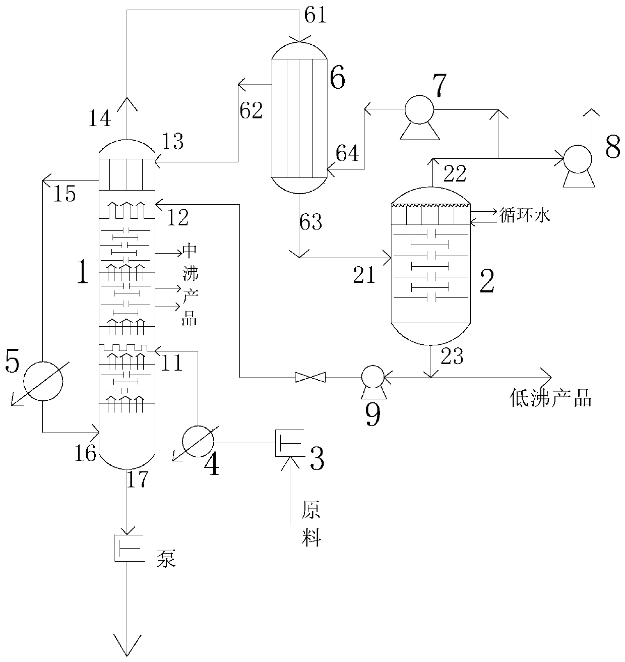
[0036] see figure 1 , an energy-saving carrier gas stripping system, comprising a stripping tower 1, a separation tank 2; a raw material heater 4; a carrier gas heater 5 and a gas circulation heat exchanger 6;

[0037] A heat-and-mass-transfer section is set in the stripping tower 1; specifically, a heat-and-mass-transfer section is set at the top of the stripping tower 1, so that the light components going up with the carrier gas pass through the heat-and-mass-transfer section for heat-exchanging and cooling , to reduce the temperature of the light components.

[0038] The stripping tower 1, the gas circulation heat exchanger 6 and the separation tank 2 are connected in sequence through pipelines; the gas circulation heat exchanger 6 is connected with the heat and mass transfer section through pipelines; the separation tank 2 is connected with the stripping tower 1 through pipelines ; The raw material heater 4 is connected to the stripping tower 1 through a pipeline; the hea...

Embodiment 2

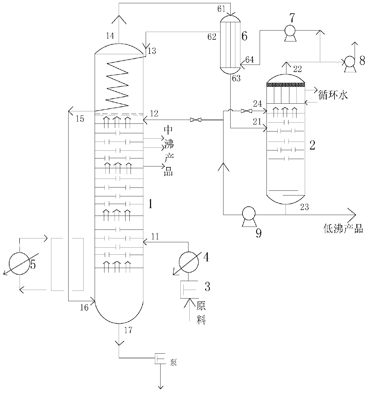
[0059] see figure 2 , an energy-saving carrier gas stripping system, comprising a stripping tower 1, a separation tank 2; a raw material heater 4; a carrier gas heater 5 and a gas circulation heat exchanger 6;

[0060] In this embodiment, the stripper 1 is provided with a raw material inlet 11, a light component reflux inlet 12, a carrier gas inlet 13, a light component outlet 14, a carrier gas outlet 15, a carrier gas circulation inlet 16 and a heavy component discharge port 17.

[0061] In this embodiment, a heat and mass transfer section is arranged at the top of the stripping tower 1; the heat and mass transfer section includes heat exchange tubes and fillers, the heat exchange tubes are coiled heat exchange tubes, and the fillers are placed in the coiled heat exchange tubes. external.

[0062] In this embodiment, the separation tank 2 is provided with a separation tank inlet 21 , a separation tank top outlet 22 , a separation tank bottom outlet 23 and a separation tank...


PUM


Abstract

The invention belongs to the technical field of stripping separation, and relates to an energy-saving carrier gas stripping system and stripping process. The energy-saving carrier gas stripping systemcomprises a gas stripping tower, a separation tank, a raw material heater, a carrier gas heater and a gas circulation heat exchanger, wherein a heat exchange and mass transfer section is arranged atthe inner top of the gas stripping tower, and the gas stripping tower, the gas circulation heat exchanger and the heat exchange and mass transfer section sequentially communicate with each other through pipelines; the gas circulation heat exchanger, the separation tank and the gas stripping tower sequentially communicate with each other through pipelines; the raw material heater communicates withthe gas stripping tower; the heat exchange and mass transfer section, the carrier gas heater and the gas stripping tower are sequentially communicate with each other through pipelines; and the heat exchange and mass transfer section comprises a heat exchange tube and a filler, and the heat exchange tube is a tubular heat exchange tube or a coiled tube type heat exchange tube. According to the invention, separation temperature is low, different carrier gas heating modes are adopted for heat exchange and mass transfer, enrichment and separation of one or more substances are achieved through stripping and rectification, separation effect is good, heat of the system is recycled, heat consumption and cold consumption of separation are reduced, and energy consumption is saved by 30%-50%.

Description

technical field [0001] The invention belongs to the technical field of stripping and separation, and relates to an energy-saving carrier gas stripping system and a stripping process. Background technique [0002] In chemical production, for the separation of some high-boiling media and high-viscosity media, conventional distillation cannot complete the separation; for the separation of some heat-sensitive media, solid-containing particle systems, and colloidal systems, traditional techniques cannot be separated; these media separations have separation The temperature is high, the viscosity of the medium is high, and the separation effect of the traditional separation technology is poor. The use of molecular distillation, short-path distillation or thin film distillation also has problems such as poor fractionation precision, large investment, high energy consumption, large land occupation, and high operation and maintenance costs. Contents of the invention [0003] Aiming ...

Claims


Application Information

Patent Timeline
Patent Type & Authority Applications(China)
IPC IPC(8): B01D3/00B01D3/10B01D3/14B01D3/32B01D3/34
CPCB01D3/007B01D3/143B01D3/32B01D3/343B01D3/10
Inventor 张海峰
Owner 陕西聚能新创煤化科技有限公司
Why Eureka
Try Eureka