Chemical dissolving device for reduction, recycling and harmless treatment of sludge

A dissolving device and reduction technology, applied in the direction of dissolving, dissolving, dissolving system, etc., can solve the problems of high labor intensity, disinfection and sterilization treatment, high labor cost, etc., achieve a high degree of mechanization, meet the needs of use, and reduce labor intensity Effect

Pending Publication Date: 2020-07-28
CHANGSHA UNIVERSITY OF SCIENCE AND TECHNOLOGY
View PDF0 Cites 3 Cited by
  • Summary
  • Abstract
  • Description
  • Claims
  • Application Information

AI Technical Summary

Problems solved by technology

[0003] The sludge produced in these rivers often contains stones, hard blocks, dead branches, etc. The existing method is to directly send the sludge produced in the rivers to the countryside for use as fertilizer. This method has the following technical problems: 1. The sludge generated in the river often contains many hard rocks, lumps, and dead branches, which not only cannot form a fertilization effect on farmland crops, but also hinder the growth of farmland crops; 2. The sludge generated in the river is often in the process of transportation. Changes in temperature and loss of water form agglomerates. The existing method of sludge treatment is to use manual feeding, which is labor-intensive, long-distance transportation, and high labor costs. It is difficult to meet the continuous processing of large-scale river sludge. 3. There is no effective chemical disinfection and sterilization treatment for river sludge, and conventional artificial addition cannot add chemical to river sludge, and the chemical cannot penetrate into the agglomerated sludge, and cannot be uniformly Sufficient mixing of sludge treatment chemicals and sludge will not only result in poor mixing effect, but also easily lead to a large waste of sludge treatment chemicals, which will result in twice the result with half the effort, resulting in a substantial increase in the production cost of sludge treatment

Method used


Image

  • Chemical dissolving device for reduction, recycling and harmless treatment of sludge
  • Chemical dissolving device for reduction, recycling and harmless treatment of sludge
  • Chemical dissolving device for reduction, recycling and harmless treatment of sludge

Examples


Embodiment Construction

[0027] In order to enable those skilled in the art to better understand the technical solution of the present invention, the present invention will be described in detail below in conjunction with the accompanying drawings. The description in this part is only exemplary and explanatory, and should not have any limiting effect on the protection scope of the present invention. .

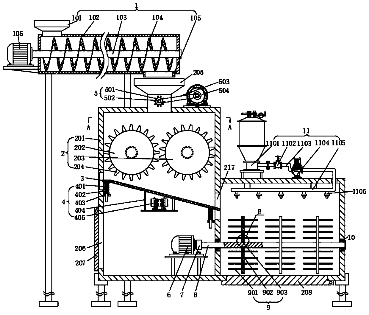
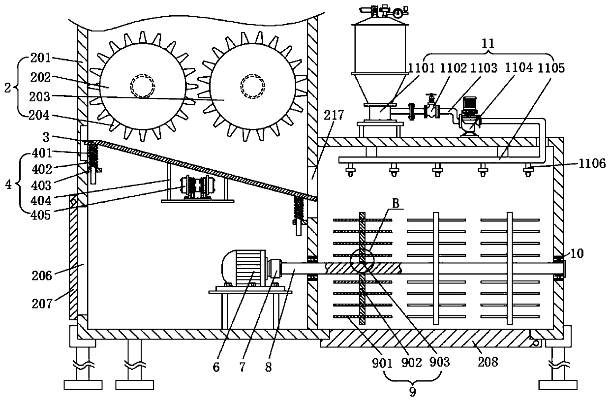
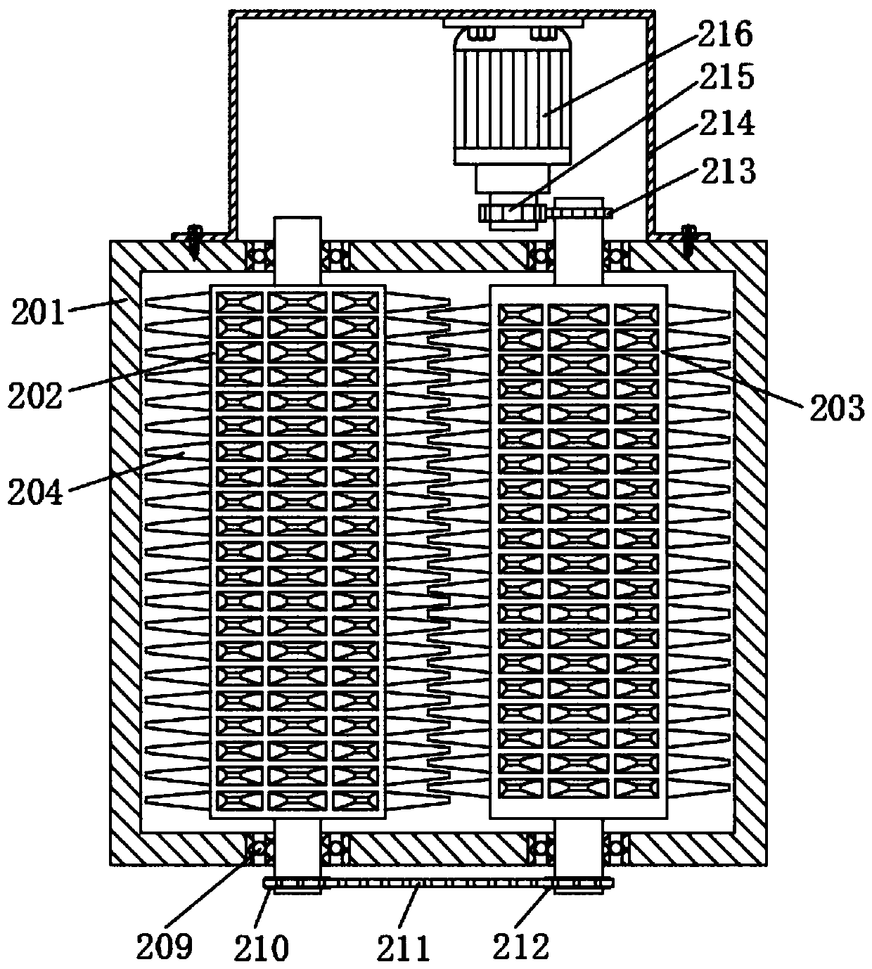
[0028] Such as Figure 1-Figure 5 As shown, the specific structure of the present invention is as follows: it includes a crushing assembly 2 for crushing sludge, and a conveying assembly 1 for conveying sludge is arranged above the crushing assembly 2. The conveying assembly 1 includes a feeding housing 102, and the feeding The upper left side of the housing 102 is provided with a feeding cylinder 101 for sludge feeding, and the bottom of the right side of the feeding housing 102 is provided with a discharge cylinder 105 for sludge discharge, and the discharge cylinder 105 is located directly above the...


PUM


Abstract

The invention discloses a chemical dissolving device for reduction, recycling and harmless treatment of sludge, belonging to the technical field of sludge treatment. The chemical dissolving device comprises a crushing assembly and a conveying assembly, wherein the conveying assembly comprises a feeding shell; a feeding cylinder is arranged at the upper end of the feeding shell; a discharging cylinder is arranged at the bottom of the right side of the feeding shell; the discharging cylinder is positioned right above a hopper; the hopper is arranged at the center of the top of a case body; a material stirring assembly is arranged in the hopper; a driven crushing roller and a driving crushing roller are arranged in the case body; a material guiding plate is obliquely and movably arranged below the case body; the right end of the material guiding plate is located in a discharging port; a vibration assembly is arranged at the bottom of the material guiding plate; a stirring rotating shaft is arranged on the right side of the discharging port; a combined stirring assembly is arranged on the stirring rotating shaft; and a dosing assembly is arranged above the combined stirring assembly. According to the invention, automatic feeding operation of river sludge can be realized, crushed sludge and a sludge treatment chemical are fully mixed and uniformly stirred, the waste of the sludge treatment chemical is avoided, and sludge treatment cost is reduced.

Description

technical field [0001] The invention relates to the technical field of sludge treatment, in particular to a chemical dissolving device for sludge reduction, resource utilization and harmless treatment. Background technique [0002] A large amount of silt and sludge are always generated and deposited in rivers and lakes, especially in rivers, lakes, and river confluences near cities or populated areas. It pollutes the environment and affects people's daily life. The sludge contains organic matter such as domestic garbage, sewage pits, manure, farmyard manure, bark, leaves, weeds, and sawdust, which has a serious impact on the ecological environment of rivers, lakes, and lakes. The silting phenomenon of rivers, rivers, lakes, and lakes makes the water bottom level far exceed the land level, which is easy to block the waterway and bring certain adverse effects. The silt in the river has increasingly affected flood control, drainage, irrigation, water supply, navigation, etc. ...

Claims


Application Information

Patent Timeline
Patent Type & Authority Applications(China)
IPC IPC(8): C02F11/00B01F1/00B01F11/00B01F13/10B02C4/08B02C4/30
CPCC02F11/00B02C4/08B02C4/30C02F2303/06C02F2103/007B01F21/402B01F21/30B01F31/441B01F33/831B01F33/83612
Inventor 赵文玉蒋朝辉刘梦月刘春华卿志和刘志华陈宏
Owner CHANGSHA UNIVERSITY OF SCIENCE AND TECHNOLOGY
Why Eureka
Try Eureka