High-frequency ultra-short electron gun grid regulation and control pulse power supply system

A technology of pulse power supply and electron gun, which is applied to electric pulse generator circuits, energy storage elements to generate pulses, and electrical components, etc., can solve the problems that the beam position and phase fluctuation are quite sensitive, and the impact is difficult to accurately evaluate.

Active Publication Date: 2020-07-28
CHONGQING UNIV
View PDF6 Cites 3 Cited by
  • Summary
  • Abstract
  • Description
  • Claims
  • Application Information

AI Technical Summary

Problems solved by technology

[0003] But in the usual petal-shaped accelerator, the electron beams in multiple radio frequency cycles are accelerated in the coaxial resonant cavity at the same time, and the electron beams will cross a

Method used


Image

  • High-frequency ultra-short electron gun grid regulation and control pulse power supply system
  • High-frequency ultra-short electron gun grid regulation and control pulse power supply system
  • High-frequency ultra-short electron gun grid regulation and control pulse power supply system

Examples


Embodiment 1

[0057] see Figure 1 to Figure 22 , a high-frequency ultra-short electron gun gate-regulated pulse power supply system for generating voltage-doubling pulses, mainly including a power supply, a control module, a charging inductor L1, a pulse forming line, a MOSFET switch tube M1, a control module and a matching load R1.

[0058] The power supply supplies power for the grid-regulated pulse power supply system of the high-frequency grid-controlled electron gun. The control module controls the on-off sequence of the MOSFET switch tube M1, so that the high-frequency ultra-short electron gun grid-regulated pulse power supply system switches between the LR charging state and the LC oscillation state. When the MOSFET switch tube M1 is turned on each time, the high-frequency extremely short electron gun grid-regulated pulse power supply system works in the LR charging state. MOSFET switch tube M1 conducts each time for t on . When the MOSFET switch tube M1 is turned off each time, ...

Embodiment 2

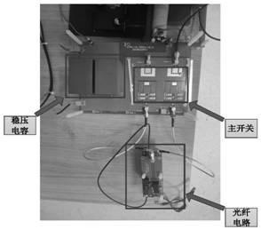
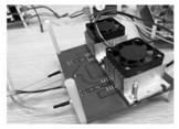
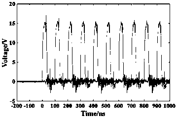
[0067] see Figure 23 to Figure 35 , a high-frequency ultra-short electron gun gate-regulated pulse power supply system for directly generating high-frequency ultra-short pulses, mainly including power supply, signal isolation control module, pulse forming line, MOSFET switch tube S, heat sink, charging resistor R c1 and matched load R L1 .

[0068] The signal isolation control module includes an FPGA, a photoelectric conversion module and a switch tube drive chip. The FPGA generates electrical signals for controlling the switch tubes and sends them to the photoelectric conversion module. The photoelectric conversion module includes a fiber optic transmitter and a fiber optic receiver. The optical fiber transmitter is connected with the wires of the FPGA module, converts the switching tube control electrical signal sent by the FPGA module into a switching tube control optical signal, and sends it to the fiber optic receiver. The optical fiber receiver is connected with the...

Embodiment 3

[0074] see Figure 36 to Figure 43 , used to generate frequency multiplied, phase-adjustable high-frequency ultra-short electron gun gate-regulated pulse power system, mainly including power supply, signal isolation control module, pulse forming line, MOSFET switch tube S1, MOSFET switch tube S2, cooling device, charging Resistance R c2 and matched load R L2 .

[0075] The signal isolation control module includes an FPGA, a photoelectric conversion module and a switch tube drive chip.

[0076] The FPGA generates electrical signals for controlling the switch tubes and sends them to the photoelectric conversion module.

[0077] The photoelectric conversion module includes a fiber optic transmitter and a fiber optic receiver.

[0078] The optical fiber transmitter is connected with the wires of the FPGA module, converts the switching tube control electrical signal sent by the FPGA module into a switching tube control optical signal, and sends it to the fiber optic receiver. ...


PUM


Abstract

The invention discloses a high-frequency ultra-short electron gun grid regulation and control pulse power supply system, which mainly comprises the following four schemes: a high-frequency ultra-shortelectron gun grid regulation and control pulse power supply system for generating voltage-multiplying pulses, a high-frequency ultra-short electron gun grid regulation and control pulse power supplysystem for directly generating high-frequency ultra-short pulses, a high-frequency ultra-short electron gun grid regulation and control pulse power supply system for generating frequency-multiplying and phase-adjustable pulses, and a high-frequency ultra-short electron gun grid regulation and control pulse power supply system for directly generating polarity and phase-adjustable pulses. Output ofvoltage-multiplying pulses, high-frequency ultra-short pulses, frequency-multiplying and phase-adjustable pulses and polarity and phase-adjustable pulses is realized respectively.

Description

technical field [0001] The invention relates to the field of pulse generation, in particular to a high-frequency ultra-short electron gun grid-regulated pulse power supply system. Background technique [0002] High-energy industrial CT is an important means of non-destructive testing and quality evaluation of high-end large-scale equipment, and the key technology breakthrough of ray source to improve the performance of high-energy industrial CT. In order to effectively solve the contradiction between the detection of large-scale and complex workpieces and high-resolution detection, and promote the transformation of high-energy industrial CT from qualitative detection to quantitative and precise measurement, it is necessary to greatly improve the spatial resolution and density resolution indicators of high-energy industrial CT and CT images. quality. Compared with the commonly used standing wave electron linear accelerator for high-energy industrial CT, the new radio frequen...

Claims


Application Information

Patent Timeline
IPC IPC(8): H02M9/02H03K3/57H05H5/02
CPCH02M11/00H03K3/57H05H5/02
Inventor 余亮马剑豪董守龙姚陈果
Owner CHONGQING UNIV
Why Eureka
Try Eureka