
Side-mounted residual oil hydrogenation emulsification bed micro-interface enhanced reaction device and method
A residual oil hydrogenation and side-mounted technology, which is applied in chemical instruments and methods, emulsification, mixing methods, etc., can solve the problems of high energy consumption and production cost, short equipment operation cycle, poor intrinsic safety, etc., and achieve reduction of material consumption, The effect of increasing the phase boundary area and accelerating the process
- Summary
- Abstract
- Description
- Claims
- Application Information
AI Technical Summary
Problems solved by technology
Method used
Image

Examples
Embodiment 1
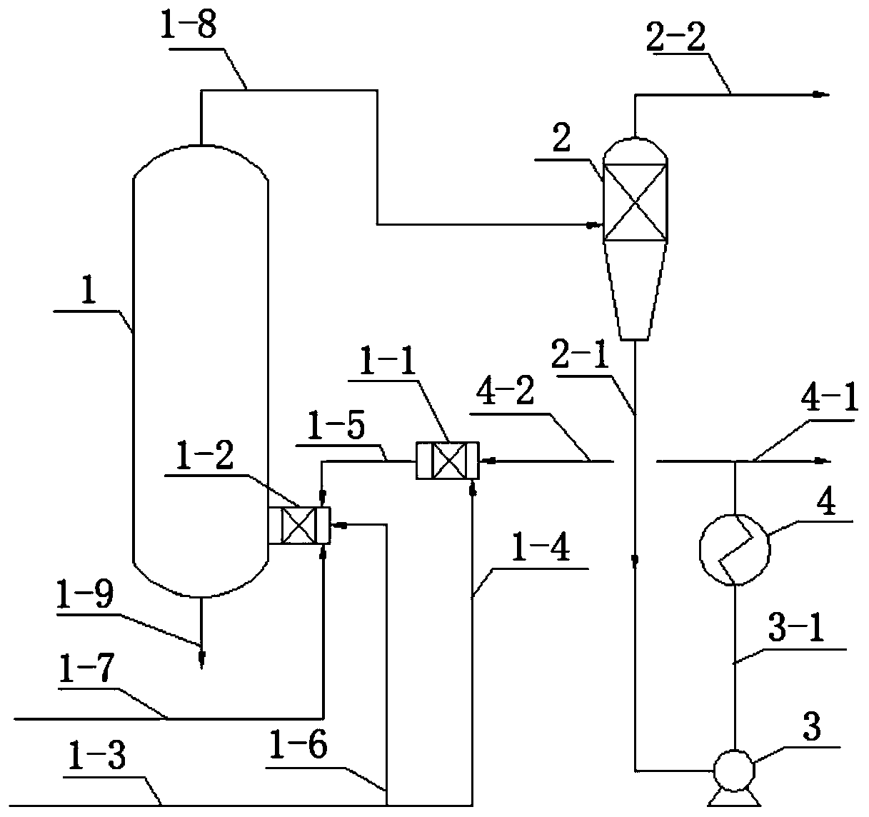
[0042] Such as figure 1 A side-mounted residue hydro-emulsified bed micro-interface strengthening reaction device shown includes a reactor main body 1; the top of which is provided with a gas-liquid discharge port, which is connected to gas-liquid discharge pipelines 1-8;
[0043] A set of bubble breakers; consists of a hydraulic bubble breaker 1-1 and a pneumatic bubble breaker 1-2 in series. The pneumatic bubble breaker 1-2 is equipped with an air inlet, which is connected to the pneumatic bubble breaker air inlet pipeline 1-6; the liquid inlet is connected to the liquid raw material pipeline 1-7; the hydraulic bubble breaker 1-1 The liquid inlet is connected to the circulating fluid pipeline 4-2; the air inlet is connected to the hydraulic air bubble breaker air inlet pipeline 1-4; the pneumatic air bubble breaker air inlet pipeline 1-6 and the hydraulic air bubble The breaker inlet pipe 1-4 is connected to the gas raw material pipe 1-3; the bubble breaker is arranged on the s...
Embodiment 2
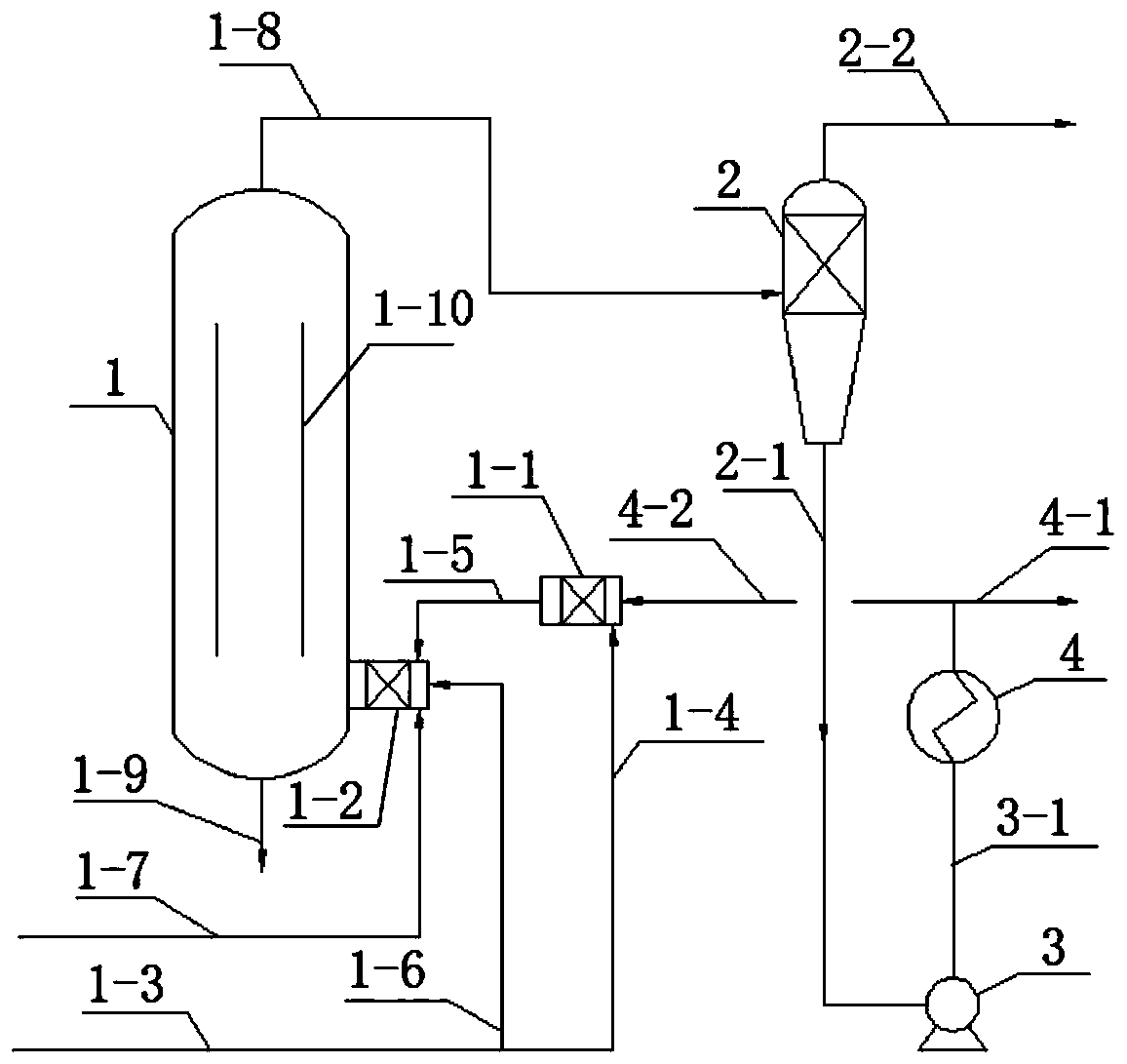
[0051] The device structure of Example 2 is as figure 2 As shown, the difference from Example 1 is that the flow guide cylinder 1-10 is provided in the reactor body 1.
[0052] The mixture of hydrogen and 60% residual oil and 40% coal tar with a mass fraction of 60% and 40% coal tar enters the bubble breaker through gas raw material pipelines 1-3 and liquid raw material pipelines 1-7 at a volume ratio of 500:1. The residual oil is sent to the pneumatic bubble breaker 1-2 from the liquid raw material pipeline 1-7; the hydrogen entering from the gas raw material pipeline 1-3 is divided into two ways, one way passes through the pneumatic bubble breaker intake pipeline 1-6 It is fed into the pneumatic bubble breaker 1-2 as the driving force for the crushing, and the other way enters the hydraulic bubble breaker 1-1 through the air inlet pipe 1-4 of the hydraulic bubble breaker. The circulating liquid sent from the circulating liquid pipeline 4-2 is broken into a primary emulsion, an...
Embodiment 3
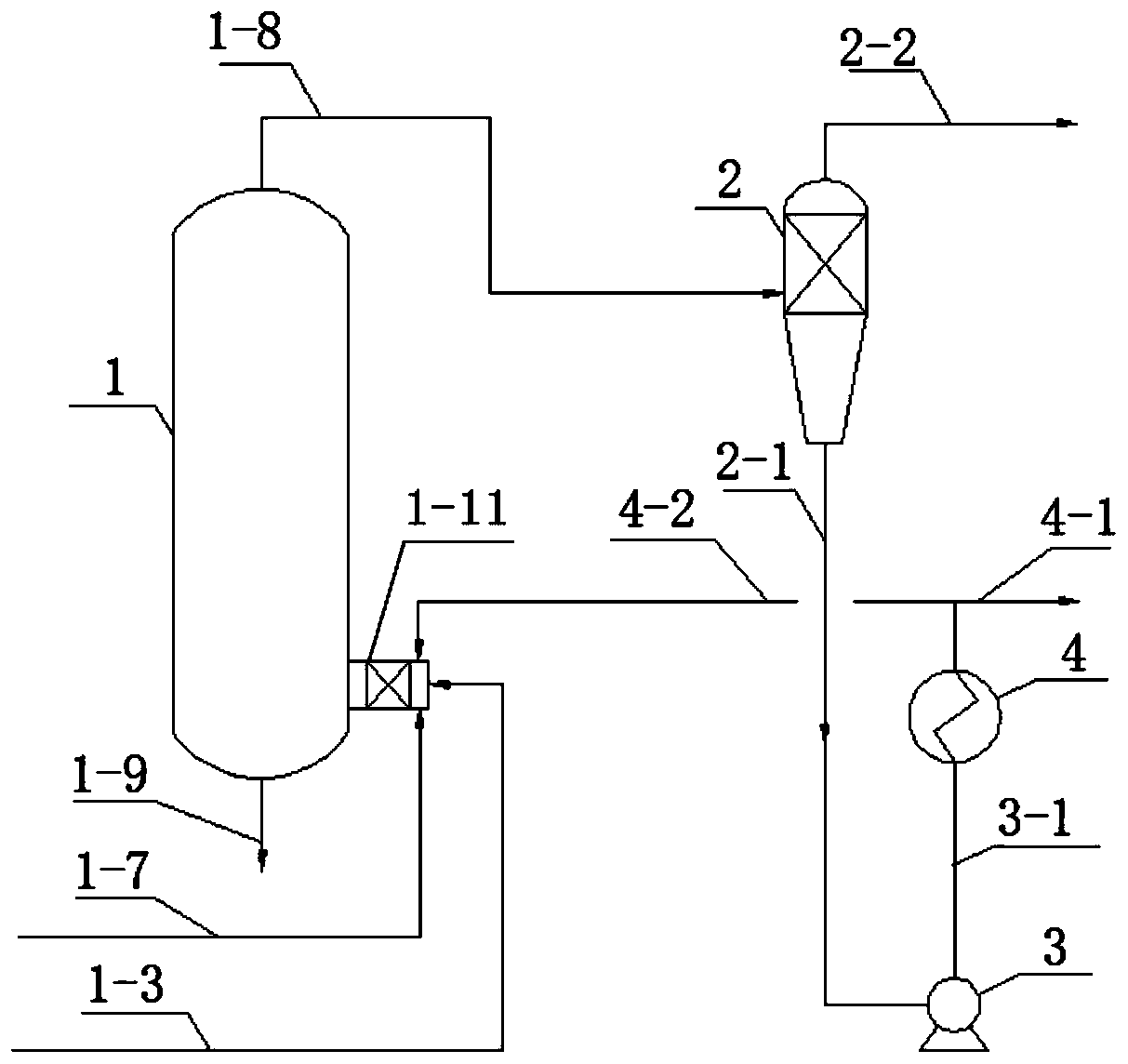
[0055] The device structure of Example 3 is as follows image 3 As shown, the difference from Embodiment 1 is that the bubble breaker uses gas-liquid linkage bubble breaker 1-11.
[0056] The mixture of 30% mass fraction residual oil and 70% coal tar and fresh hydrogen enter the bubble breaker 1- through the gas raw material pipeline 1-3 and the liquid raw material pipeline 1-7 at a volume ratio of 1:1800. 11 in. Maintain pressure at 12MPa, temperature control at 470℃, use carbon-supported iron-based catalyst, and space velocity at 1.5h -1 . In the bubble breaker 1-11, the circulating fluid sent through the circulating fluid pipeline 4-2 is broken into a gas-liquid system of 10μm-100μm microbubbles, and then enters the reactor body 1 to form a vortex to continue the reaction, and the emulsification system stops reacting After staying in the main body for 2.5 hours, it enters the gas-liquid separator 2 through the top gas-liquid discharge line 1-8, and the separated gas is sent t...
PUM
| Property | Measurement | Unit |
|---|---|---|
| diameter | aaaaa | aaaaa |
Abstract
Description
Claims
Application Information