Urea catalytic hydrolysis generator capable of recycling catalyst and catalytic hydrolysis method

A technology for catalytic hydrolysis and catalytic hydrolysis of urea, applied in the field of catalytic hydrolysis generators and catalytic hydrolysis of urea, can solve the problems of difficult recycling, difficult separation, long time consumption, etc., so as to overcome the disadvantages of recycling and strengthen the effect of stripping. , the effect of accelerating the hydrolysis reaction

Pending Publication Date: 2020-08-04
JINAN SHANYUAN ELECTRIC POWER EQUIP
View PDF6 Cites 4 Cited by
  • Summary
  • Abstract
  • Description
  • Claims
  • Application Information

AI Technical Summary

Problems solved by technology

[0005] "A urea catalytic hydrolysis ammonia production system for flue gas denitrification" (201920470300.4), "Urea catalytic hydrolysis device" (201822129821.1), "A urea catalytic hydrolysis ammonia production system and method using waste heat" (201710151844.X) patent " A method and device for catalytic hydrolysis of urea" (201310344322.3) uses phosphate as a catalyst to prepare ammonia gas for denitrification by catalytic hydrolysis of urea. The catalyst used in this technology is a homogeneous catalyst. After the catalyst and urea solution are miscible, it is difficult to separate. Facilitate the problem of catalyst recycling; Patent US4220635 adopts a series of vanadium compounds (for example: Na 3 VO 4 、NaVO 4 •nH 2 O, V 2 o 5 and VOSO 4 •nH 2 O, etc.) as a catalyst to treat wastewater with a urea content of 0.05wt.%~10wt.%, the reaction time lasts 360 minutes, and the urea hydrolysis rate can only reach 58%, which takes a long time, and the catalyst used is a homogeneous catalyst , it is difficult to recycle, the required amount of catalyst is large, the cost is high, it is not suitable for industrial urea wastewater treatment, and it is not suitable for the preparation of ammonia for denitrification in industry; the patent "a solid catalyst catalytic hydrolysis of low concentration urea wastewater Metho

Method used


Image

  • Urea catalytic hydrolysis generator capable of recycling catalyst and catalytic hydrolysis method

Examples


Embodiment Construction

[0029] For ease of description, spatially relative terms such as "upper," "lower," "left," and "right" may be used herein to describe the relationship of one element or feature relative to another element or feature shown in the figures. It will be understood that the spatial terms are intended to encompass different orientations of the device in use or operation in addition to the orientation depicted in the figures. For example, if the device in the figures is turned over, elements described as "below" other elements or features would then be oriented "above" the other elements or features. Thus, the exemplary term "lower" can encompass both an orientation of above and below. The device may be otherwise oriented (rotated 90 degrees or at other orientations) and the spatially relative specifications used herein interpreted accordingly.

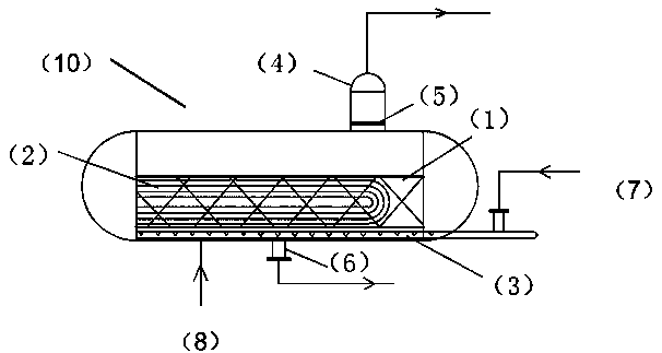
[0030] attached figure 1 It is a schematic diagram of a specific embodiment of the present invention, a urea catalytic hydrolysis generato...


PUM


Abstract

The invention discloses a urea catalytic hydrolysis generator capable of recycling a catalyst. The hydrolysis generator comprises a hydrolysis generator body, a steam injection system is arranged at the bottom in the hydrolysis generator body, a heater is arranged at the upper end of the steam injection system, a catalyst box is installed on one side of the heater, a gas collector is arranged on the hydrolysis generator body, and a urea inlet is formed in the lower end of the hydrolysis generator body. The invention discloses a urea catalytic hydrolysis method using the urea catalytic hydrolysis generator capable of recycling a catalyst. The urea catalytic hydrolysis method comprises the following steps: a catalytic membrane is prepared; the catalytic membrane is placed in a catalyst box after being broken to form a catalytic layer; a urea solution is introduced into the hydrolysis generator and is in contact with the catalytic layer; the heater heats the catalyst layer and urea, and meanwhile steam enters the steam injection system from the steam inlet to intensify turbulence of the reaction solution. The super-strong solid acid is immobilized on the membrane, so that the immobilization of the catalyst is realized, the problem that a homogeneous catalyst is not beneficial to recycling is solved, and the ammonia yield is high.

Description

technical field [0001] The invention relates to the field of urea catalytic hydrolysis, in particular to a urea catalytic hydrolysis generator capable of recycling a catalyst and a catalytic hydrolysis method. Background technique [0002] With the gradual improvement of national environmental protection standards and the increasing intensity of environmental protection supervision year by year, environmental protection issues in the power industry have received widespread attention. The denitrification device is an important device for the power industry to achieve NOx discharge standards. In recent years, thermal power plants have successively undergone denitrification transformation. SCR flue gas denitrification technology is currently the mainstream technology for denitrification. It uses ammonia as a reducing agent, and under the action of a catalyst, nitrogen oxides are reduced to nitrogen and water that are harmless to the atmosphere, thereby achieving the purpose of ...

Claims


Application Information

Patent Timeline
IPC IPC(8): B01J8/02C01C1/08B01D53/86B01D53/56B01J21/06B01J27/053B01J35/06
CPCB01J8/0242B01J8/0285C01C1/086B01D53/8625B01J21/066B01J27/053B01J35/065B01D2258/0283B01D2251/2062Y02P20/52Y02P20/584
Inventor 曹姗姗田超黄修帅韩淑媛陈国利杨玉涛
Owner JINAN SHANYUAN ELECTRIC POWER EQUIP
Why Eureka
Try Eureka