
Horizontal deacidification furnace for producing high-temperature water vapor based on hydrogen combustion method

A high-temperature steam and combustion technology, applied in the direction of silica, silicon oxide, etc., can solve the problems of low deacidification efficiency, low quality and serious agglomeration of fumed silica, and achieve low energy consumption and stable and uniform airflow. , the effect of uniform temperature distribution

Active Publication Date: 2020-08-04
ZHEJIANG JINGGONG NEW MATERIAL TECH
View PDF8 Cites 0 Cited by
  • Summary
  • Abstract
  • Description
  • Claims
  • Application Information

AI Technical Summary

Problems solved by technology

[0005] The invention provides a horizontal deacidification furnace for producing high-temperature water vapor based on the hydrogen combustion method, which can effectively solve the problems of low deacidification efficiency, low quality and serious agglomeration of gas-phase white carbon black in traditional deacidification furnaces

Method used


Image

  • Horizontal deacidification furnace for producing high-temperature water vapor based on hydrogen combustion method
  • Horizontal deacidification furnace for producing high-temperature water vapor based on hydrogen combustion method
  • Horizontal deacidification furnace for producing high-temperature water vapor based on hydrogen combustion method

Examples


Embodiment 1

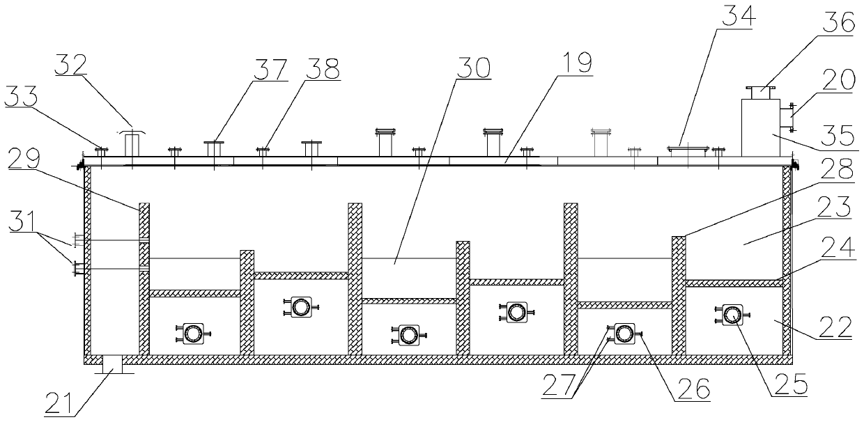
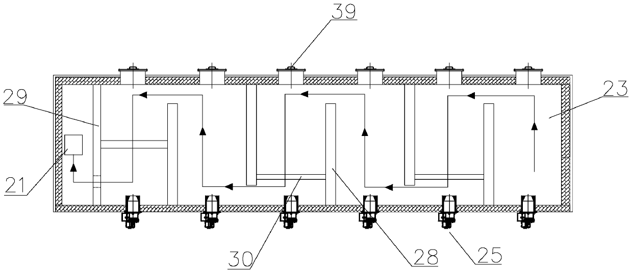
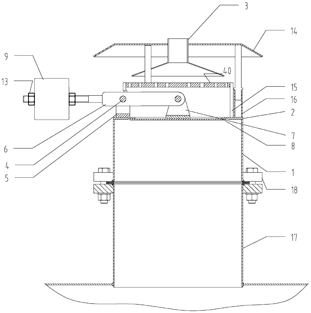
[0063] like figure 1 Shown, a kind of horizontal deacidification furnace that produces high-temperature water vapor based on the hydrogen combustion method includes a body of furnace 19, and the top of the head end of the body of furnace is provided with a cyclone separator 35; the cyclone separator is provided with an exhaust port 36 and The feed port 20, the bottom of the tail end is provided with a discharge port 21; the bottom of the furnace body is provided with six combustion chambers 22, and the top of the combustion chamber is a fluidization chamber 23, and a gas distributor 24 is passed between the combustion chamber and the fluidization chamber Isolation; each combustion chamber is provided with a burner 25; each burner is provided with a hydrogen inlet 26 and two air inlets 27; the fluidization chamber is provided with five staggered baffles 28 to form an S-shaped flow Road (such as figure 2 As shown), the rear end of the baffle at the end is provided with a barri...


PUM


Abstract

The invention relates to the field of chemical equipment, and discloses a horizontal deacidification furnace for producing high-temperature water vapor based on a hydrogen combustion method, wherein the horizontal deacidification furnace comprises a furnace body, the head end of the furnace body is provided with a feed port, and the tail end of the furnace body is provided with a discharge port; aplurality of combustion chambers are arranged at the bottom of the furnace body, fluidization chambers are arranged at the tops of the combustion chambers, and the combustion chambers are isolated from the fluidization chambers through gas distributors; each combustion chamber is provided with a combustor; a baffling baffle plate is arranged in each fluidization chamber, and a blocking plate is arranged at the rear end of the baffling baffle plate at the tail end; material level control baffle plates are arranged between the plurality of adjacent baffling baffle plates and between the baffling baffle plate at the tail end and the blocking plate; a conical plug is arranged on the side wall of the tail end of the furnace body, penetrates through the furnace body and is fixed on the blockingplate; and an automatic breather valve, a hot air purging port and a tail gas exhaust port are arranged at the top of the furnace body. The problems that a traditional deacidification furnace is lowin gas-phase white carbon black deacidification efficiency, low in quality and serious in agglomeration can be effectively solved. In addition, airflow in the deacidification furnace is stable and uniform, the temperature control effect is good, and energy consumption is low.

Description

technical field [0001] The invention relates to the field of chemical equipment, in particular to a horizontal deacidification furnace for producing high-temperature steam based on a hydrogen combustion method. Background technique [0002] Fumed silica, with extremely small particle size and large specific surface area, has excellent stability, reinforcement, thickening and thixotropy, and is widely used in rubber, adhesives, coatings, paints, cosmetics and other industrial fields. In the production process of fumed silica, chlorosilane or monomethyltrichlorosilane is used for high-temperature hydrolysis, and hydrogen chloride is produced during the hydrolysis process, because the specific surface area of ​​fumed silica is large (150-400m 2 / g), the surface of nano-sized particles is easy to adsorb hydrogen chloride molecules, and the crude fumed silica product needs to be deacidified. [0003] At present, the white carbon black deacidification technology is divided into c...

Claims


Application Information

Patent Timeline
IPC IPC(8): C01B33/18
CPCC01B33/18
Inventor 厉鑫强
Owner ZHEJIANG JINGGONG NEW MATERIAL TECH
Learn More