Eureka AIR delivers breakthrough ideas for toughest innovation challenges, trusted by R&D personnel around the world.

Reversed-polarity AlGaInP red light LED chip structure and manufacturing method thereof

A production method and reverse polarity technology, which is applied in the direction of electrical components, circuits, semiconductor devices, etc., can solve the problems of difficult main electrode ITO production and limited welding wire yield, so as to improve the welding wire yield and improve the welding efficiency. The effect of enhancing the line yield and adhesion performance

Active Publication Date: 2020-08-04
SHANDONG INSPUR HUAGUANG OPTOELECTRONICS
View PDF3 Cites 1 Cited by
  • Summary
  • Abstract
  • Description
  • Claims
  • Application Information

AI Technical Summary

Problems solved by technology

According to the traditional packaging process, the wire bonding is carried out on the main electrode. From the design method of the present invention, it is difficult to realize the production of ITO on the main electrode, and only make the ITO film on the extended electrode. Improvement is relatively limited

Method used


Image

  • Reversed-polarity AlGaInP red light LED chip structure and manufacturing method thereof
  • Reversed-polarity AlGaInP red light LED chip structure and manufacturing method thereof
  • Reversed-polarity AlGaInP red light LED chip structure and manufacturing method thereof

Examples


Embodiment 1

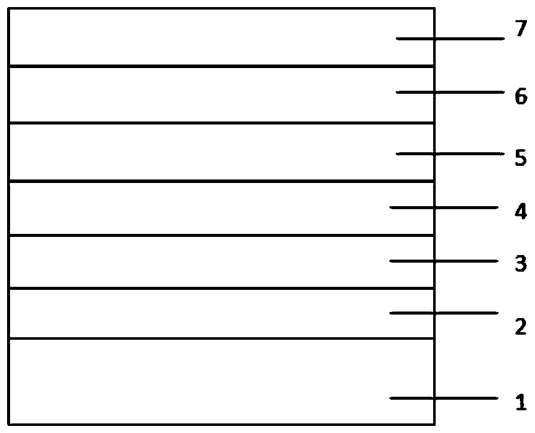
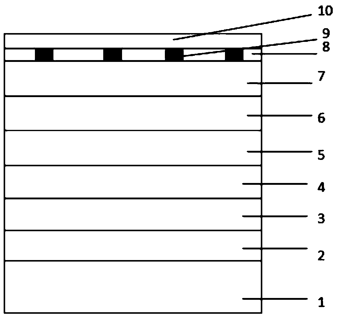
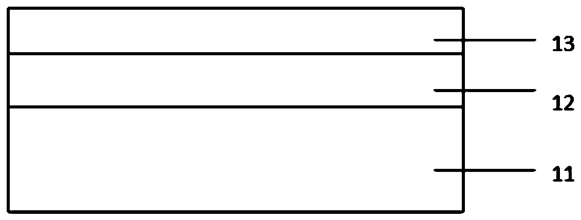
[0066] A reverse polarity AlGaInP red LED tube core structure, such as Figure 14 As shown, it includes N-face electrode 18, permanent silicon substrate 11, second mirror layer 12, metal adhesion layer 13, first mirror layer 10, SiO2 barrier layer 8 and ohmic contact layer 9 from bottom to top. , P-GaAs layer 7, P-AlGaInP layer 6, MQW quantum well layer 5, N-AlGaInP layer 4, N-GaAs layer 3 and ITO film layer 15 and SiO2 protective layer 17, extended electrode 14, main electrode 16;

[0067] The surface of the P-AlGaInP layer 6 has been roughened; the main electrode 16 is arranged on part of the ITO film layer 15; the SiO2 protection layer 17 fills the gap between the part of the ITO film layer 15 and the remaining part of the ITO film layer 15, and covers the remaining part The ITO film layer 15 and the extended electrode 14 are arranged on the N-GaAs layer 3 .

[0068] Use the ITO film layer 15 to replace the AlGaInP layer to directly contact the main electrode 16, and utili...

Embodiment 2

[0074]According to a kind of reverse polarity AlGaInP red light LED pipe core structure described in embodiment 1, its difference is that, the thickness of ITO film layer 15 is 20 angstroms;

Embodiment 3

[0076] According to a kind of reverse polarity AlGaInP red light LED pipe core structure described in embodiment 1, its difference is that, the thickness of ITO film layer 15 is 50 angstroms;


PUM

PropertyMeasurementUnit
thicknessaaaaaaaaaa
thicknessaaaaaaaaaa
widthaaaaaaaaaa

Abstract

The invention relates to a reversed-polarity AlGaInP red light LED chip structure and a manufacturing method thereof, and belongs to the technical field of semiconductor processing. The method comprises the following specific steps: (1) carrying out wafer bonding; (2) removing a substrate; (3) manufacturing an extended electrode; (4) manufacturing a roughened layer; (5) manufacturing an ITO adhesive layer; (6) manufacturing a main electrode; (7) manufacturing a protective layer; and (8) manufacturing a chip. According to the invention, through the manufacturing of the thin ITO film layer, theadhesion firmness between the metal main electrode and ITO is enhanced, great improvement of the bonding wire yield is realized; through the manufacturing of the thin ITO + SiO2 film layer, the interface total reflection is reduced, and the light emitting efficiency of the chip is improved; the whole manufacturing process is simple in principle, and the use process method is simple and convenient;the chip manufactured through the method is stable in overall quality, high in yield and good in overall stability; and the method is suitable for the manufacturing process of all reversed-polarity AlGaInP-based red light LED chips.

Description

technical field [0001] The invention relates to a reverse polarity AlGaInP red light LED tube core structure and a manufacturing method thereof, belonging to the technical field of semiconductor processing. Background technique [0002] A light-emitting diode, referred to as LED (Light Emitting Diode), is a solid-state electroluminescent (EL) semiconductor device that converts electrical energy into light energy. High-brightness and high-power AlGaInP red light LED is a common visible light LED that has been widely developed in recent years. AlGaInP quaternary red light LED has many advantages such as strong current bearing capacity, high luminous efficiency and high temperature resistance. The application in has an irreplaceable position and is widely used in various fields of lighting. [0003] At present, there are still two major problems in large-scale production of high-power AlGaInP reverse polarity red LEDs, one is the luminous brightness, and the other is the probl...

Claims


Application Information

Patent Timeline
Patent Type & Authority Applications(China)
IPC IPC(8): H01L33/06H01L33/40H01L33/46H01L33/30H01L33/00
CPCH01L33/0062H01L33/06H01L33/30H01L33/40H01L33/46
Inventor 徐晓强张兆喜吴向龙闫宝华王成新
Owner SHANDONG INSPUR HUAGUANG OPTOELECTRONICS
Why Eureka
Eureka Blog
Learn More