Microfluidic PCR chip

A microfluidic and chip technology, applied in the field of microfluidic PCR chip and microfluidic, can solve the problems of complex structure, large volume, limited temperature control response, etc., and achieve high transparency, good compatibility, accurate and fast temperature control and the detection effect

Active Publication Date: 2020-08-07
HARBIN INST OF TECH
View PDF19 Cites 1 Cited by
  • Summary
  • Abstract
  • Description
  • Claims
  • Application Information

AI Technical Summary

Problems solved by technology

[0007] In order to solve the technical problems of the existing microfluidic PCR chip system with large volume, complex structure and limited temperature control response, the present invention provides a microfluidic PCR chip

Method used


Image

  • Microfluidic PCR chip
  • Microfluidic PCR chip
  • Microfluidic PCR chip

Examples


specific Embodiment approach 1

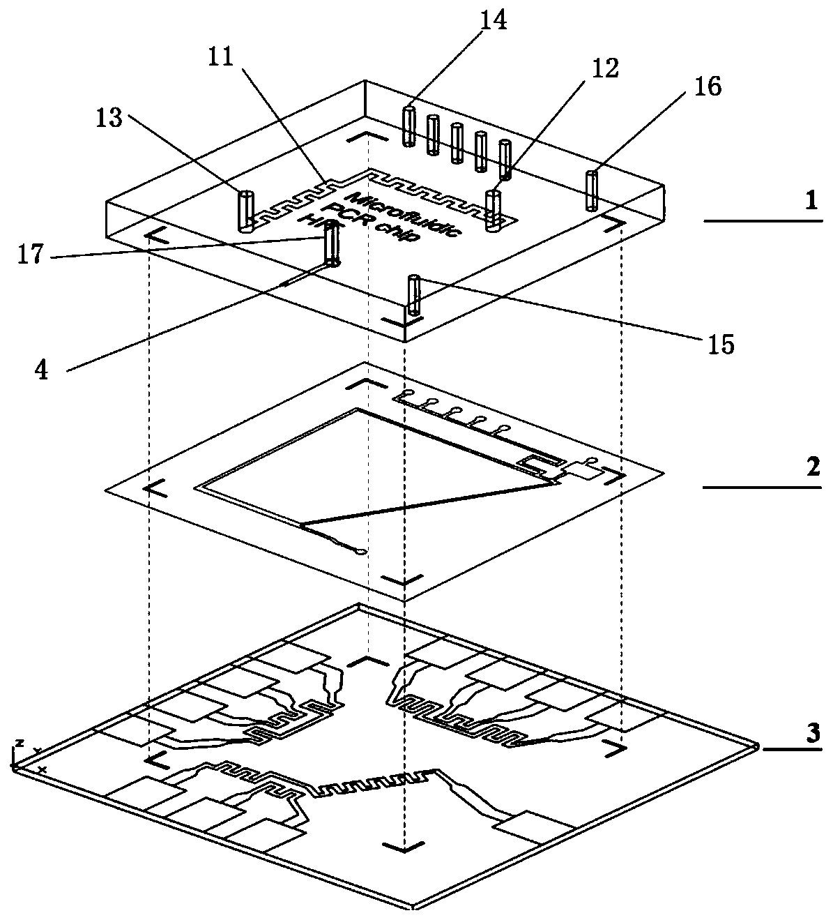
[0026] A microfluidic PCR chip, which is an on-chip temperature-controlled, temperature-difference-driven microfluidic PCR chip, comprising an integrated control cooling plate 1, a microfluidic reaction plate 2, and a temperature control plate 3. The microfluidic The reaction plate 2 is arranged between the control cooling plate 1 and the temperature control plate 3. The lower surface of the microfluidic reaction plate 2 is provided with a feed channel 21, a mixing channel 22, a pressure balance channel 23, and an annular circulation channel. 24 and a discharge flow channel 25, the feed flow channel 21 is in communication with one end of the mixing flow channel 22, and the other end of the mixing flow channel 22, the pressure balance flow channel 23 and the discharge flow channel 25 are all connected with the annular circulating flow The channel 24 is in communication, the feed channel 21, the mixing channel 22 and the pressure balance channel 23 are all located at the upper par...

specific Embodiment approach 2

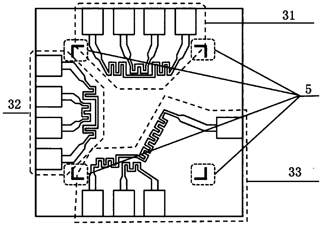
[0037] The difference between this embodiment and the first embodiment is that the three parts of the annealing temperature control unit 31, the extension temperature control unit 32 and the denaturation temperature control unit 33 are at the same temperature, and the liquid position in the PCR cycle is unchanged. The reaction reagent selects the raw materials required for constant temperature PCR. Others are the same as the first embodiment.

specific Embodiment approach 3

[0039] This embodiment is different from the first embodiment in that the temperature of the annealing temperature control unit 31, the extension temperature control unit 32 and the denaturation temperature control unit 33 are the same, and the temperature of all heating elements is controlled synchronously in accordance with the denaturation, annealing, and extension Sequence loop. The liquid position does not change in the PCR cycle. Others are the same as the first embodiment.


PUM

PropertyMeasurementUnit
Thicknessaaaaaaaaaa
Resistanceaaaaaaaaaa
Sizeaaaaaaaaaa

Abstract

The invention relates to a microfluidic PCR chip. The invention belongs to the field of mechanical design and manufacturing and microfluidic control. According to the specific scheme, the microfluidicPCR chip comprises a control cooling plate, a microfluid reaction plate and a temperature control plate which are integrated together. The microfluid reaction plate is arranged between the control cooling plate and the temperature control plate; a feeding flow channel, a mixing flow channel, a pressure balancing flow channel, an annular circulating flow channel and a discharging flow channel arearranged on the microfluid reaction plate; the feeding flow channel is communicated with one end of the mixing flow channel, the other end of the mixing flow channel, the pressure balance flow channeland the discharging flow channel are all communicated with the annular circulating flow channel, the feeding flow channel, the mixing flow channel and the pressure balance flow channel are all located on the upper portion of the annular circulating flow channel, and the discharging flow channel is arrangedat the bottom of the annular circulating flow channel. Fluid in the micro-channel is drivenby heat flow circulation, so that the whole structure of the PCR chip is simplified, integrated and miniaturized, and on-chip temperature control and detection are realized more accurately.

Description

Technical field [0001] The invention belongs to the field of mechanical design and manufacturing and microfluidics, and specifically relates to a microfluidic PCR chip. Background technique [0002] PCR is currently the most common nucleic acid amplification reaction, which can specifically amplify specific low-concentration double-stranded deoxyribonucleic acid (DNA) fragments in vitro within one or two hours. PCR technology can be used in a variety of occasions such as genetic analysis, medical diagnosis, food safety, and forensic identification. The classic PCR technique mainly includes 5 steps: pretreatment (sample processing, nucleic acid extraction and reagent addition, etc.), high temperature denaturation (DNA denaturation to form two single strands, ~95°C), low temperature annealing (DNA single strand and primer renaturation, 55°C-62°C), temperature-appropriate extension (double the daughter strand extension DNA, ~72°C), and post-processing (collection and electrophoresi...

Claims


Application Information

Patent Timeline
IPC IPC(8): C12M1/00C12M1/38C12M1/34
CPCB01L3/5027B01L7/52B01L2200/12B01L2300/0819B01L2300/12
Inventor 李松晶杨天航符海姜艳邓湘
Owner HARBIN INST OF TECH
Why Eureka
Try Eureka