Target holder applied to pulsed laser co-deposition and mounting method

A technology of pulsed laser and installation method, which is applied in ion implantation plating, metal material coating process, coating, etc., can solve the problems of target loss, center of bombardment circles not coincident, and pits, etc., so as to improve the utilization rate , Slow down the speed of scrapping, avoid the effect of pits

Active Publication Date: 2020-08-11
HENAN UNIVERSITY
View PDF7 Cites 2 Cited by
  • Summary
  • Abstract
  • Description
  • Claims
  • Application Information

AI Technical Summary

Problems solved by technology

When the target is self-propagating, if the focus is on the center of the circle, the center of the target will be highly consumed. If the focus is on a non-center position, the target will be highly consumed in a ring with the axis of the target holder as the center of the circle. In this way, the consumption of the target There will be obvious differences; in addition, the entire target must be replaced after the material on any part of the target deposition surface is consumed to the limit, which cannot realize the full utilization of the target material, which not only causes material waste, but also Increase the cost burden of the enterprise. Due to the low utilization rate of the target material, it is necessary to replace the target frequently, and frequent replacement of the target will shorten the maintenance cycle of the equipment, which will affect the capacity utilization of the equipment.
When the existing full-piece target is placed in the target holder, the center of the circular target cannot coincide with the center of the target holder, and the eccentric distance of the placement is random, which will cause the center of the bombardment ring to not coincide. It will lead to uneven bombardment position, resulting in uneven utilization of the entire target, serious local loss of the target, and pits, which accelerate the scrapping of the target

Method used


Image

  • Target holder applied to pulsed laser co-deposition and mounting method
  • Target holder applied to pulsed laser co-deposition and mounting method
  • Target holder applied to pulsed laser co-deposition and mounting method

Examples


Embodiment 1

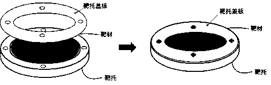
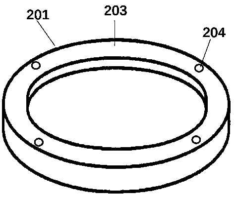
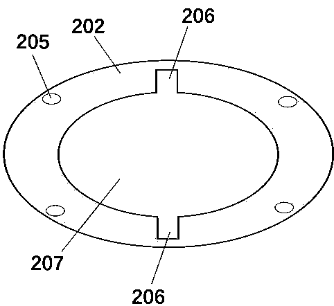
[0028] A target support applied to pulsed laser co-deposition, comprising a target support base 201 ( figure 2 ) and target cover plate 202 ( image 3 ), the target support base 201 is provided with a raised surrounding wall 203 and a circular groove, and a plurality of screw holes 204 are provided on the surrounding wall 203. The target support is set in cooperation with the target material, and the target material includes Disassembled circular target module 101 and circular target module 102 ( Figure 4 ), the side walls of the circular target module 101 and the annular target module 102 are provided with a through hole, and a through column 104 is arranged in the through hole; the target cover plate 202 also has two oppositely arranged adjustment In the zone 206 , both ends of the through column 104 are placed in the adjustment zone 206 .

[0029] The target cover plate 202 is ring-shaped, the outer diameter of the ring is equal to the outer diameter of the target suppo...

Embodiment 2

[0033] A target material matched with the target holder in Embodiment 1, which is set in the process chamber of multi-pulse laser deposition (PLD). The target includes a circular target module 101 and a plurality of circular target modules 102 that can be independently disassembled, wherein the side walls of the circular target module 101 and the multiple circular target modules 102 have Through-hole, the through-pillar 104 passes through the through-hole of the circular target module 101 and the circular target module 102, and fixes a circular target module 101 and multiple circular target modules 102 into a circular target , both ends of the through column 104 are exposed, and the through column 104 is provided with a scale mark. The length of the through post 104 is equal to the inner diameter of the target holder groove. In order to facilitate target installation, the diameter of the combined circular target is smaller than the inner diameter of the target holder. There ...

Embodiment 3

[0035] The installation method of embodiment 1 target support and embodiment 2 target material, the steps are as follows:

[0036] Step 1, a circular target module 101, one or more circular target modules 102 and circular isolation modules 105 that can be independently disassembled are combined into a circular target, wherein the circular target module 101 and one Or a plurality of annular target modules 102 are aligned with the through holes of the side walls of the annular isolation module;

[0037] Step 2, the through-pillar 104 passes through the through-holes of the circular target module 101 and the annular target module 102, so that the combined targets are integrated, and the scale marks are exposed at both ends of the through-pillar 104;

[0038] Step 3, put the combined target inserted into the through column 104 into the circular groove of the target support bottom 201, and cover the target cover plate 202;

[0039] Step 4, after aligning the screw holes of the targe...


PUM


Abstract

The invention provides a target holder applied to pulsed laser co-deposition and a mounting method of the target holder. The target holder comprises a target holder bottom and a target cover plate. Aprotruding peripheral wall is formed in the periphery of the target holder bottom, a round groove is formed in the middle of the target holder bottom, multiple screw holes are formed in the peripheralwall, and the target holder cooperates with a target. The target comprises a round target module and an annular target module, wherein the round target module and the annular target module can be independently dismounted and mounted. Through holes are formed in the side walls of the round target module and the annular target module, and through columns are arranged in the through holes. Two oppositely-arranged adjusting regions are further arranged on the target cover plate, and the two ends of the through columns are arranged in the adjusting regions. By means of the target holder, the position of the target can be arranged and fixed in the process of mounting the target, and the bombarded position of the target is effectively controlled. The utilization rate of the whole target is increased, pits generated by local losses of the target are avoided, and the scrapping speed of the target is reduced.

Description

technical field [0001] The invention relates to the field of manufacturing and processing semiconductors, in particular to a target holder applied to pulse laser co-deposition and an installation method. Background technique [0002] With the development of modern science and technology, thin film science has become one of the rapidly developing subject areas in recent years, and it is an important research field of condensed matter physics and material science. Functional thin film is the main aspect of thin film research. It not only has rich physical connotation, but also has a very wide range of applications in the fields of microelectronics, optoelectronics, and superconducting materials. [0003] For a long time, people have invented a variety of film-making technologies and methods: vacuum evaporation deposition, ion beam sputtering, magnetron sputtering deposition, molecular beam epitaxy, metal organic chemical vapor deposition, sol-gel method, etc. The above method...

Claims


Application Information

Patent Timeline
Patent Type & Authority Applications(China)
IPC IPC(8): C23C14/28
CPCC23C14/28
Inventor 郁彩艳白莹赵慧玲尹延锋
Owner HENAN UNIVERSITY
Why Eureka
Try Eureka