
Transformer and preparation method thereof

A transformer and magnetic core technology, applied in the field of transformers, can solve the problems of low efficiency, poor stability and long magnetic circuit of the transformer, and achieve the effects of reducing the length of the magnetic circuit, reducing the number of coil turns, and reducing the volume

Inactive Publication Date: 2020-08-11
DONGGUAN MENTECH OPTICAL & MAGNETIC CO LTD
View PDF0 Cites 4 Cited by
  • Summary
  • Abstract
  • Description
  • Claims
  • Application Information

AI Technical Summary

Problems solved by technology

However, in the above-mentioned transformer structure, since the magnetic circuit is long and cannot form a closed magnetic circuit, if the required saturation current capability is to be achieved, more winding coils are required, and the volume of the transformer is still relatively large.
Moreover, under normal circumstances, in the above-mentioned transformers, the inductance requirements are met by grinding the air gap in the magnetic core. This method requires high-precision grinding equipment, and the cost is high, and the inductance accuracy error is usually maintained at about ±5%. low efficiency and poor stability

Method used


Image

  • Transformer and preparation method thereof
  • Transformer and preparation method thereof
  • Transformer and preparation method thereof

Examples


Embodiment Construction

[0033] Specific embodiments of the present disclosure will be described in detail below in conjunction with the accompanying drawings. It should be understood that the specific embodiments described here are only used to illustrate and explain the present disclosure, and are not intended to limit the present disclosure.

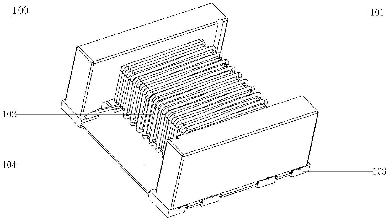
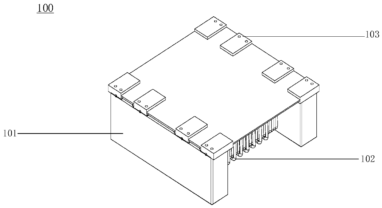
[0034] figure 1 is a structural schematic diagram of a transformer front according to an exemplary embodiment, as shown in figure 1 As shown, the transformer 100 includes: a transformer body (including a magnetic core 101 and a winding coil 102 ), an electrode pin 103 and a potting layer 104 , and the winding coil 102 is wound on the magnetic core 101 . The magnetic core 101 refers to a sintered magnetic metal oxide composed of various iron oxide mixtures (for example, manganese-zinc ferrite and nickel-ferrite are typical magnetic core materials), which are usually used in various electronic equipment coils and transformers. The coils are insulated from ea...


PUM

PropertyMeasurementUnit
Diameteraaaaaaaaaa
Coating thicknessaaaaaaaaaa

Abstract

The invention relates to a transformer and a preparation method thereof. The transformer comprises a transformer body, electrode pins and a glue pouring layer, wherein the transformer body comprises amagnetic core and a winding coil, the winding coil is wound on the magnetic core, the electrode pins are connected with the joint of the winding coil and are attached to one side of the magnetic core, the glue pouring layer is coated on the outer side of the transformer body, covers one surfaces, attached to the magnetic core, of the electrode pins, and wraps and is cured on the outer side of theclosed magnetic circuit of the magnetic core, and the glue pouring layer is made of an epoxy glue and magnetic powder. According to the transformer, the outer side of the transformer can be coated with the glue pouring layer made of the epoxy glue and the magnetic powder so as to reduce the length of the magnetic circuit of the magnetic core of the transformer, and the number of turns of coils wound on the magnetic core is reduced under the same saturation current capacity so as to reduce the size of the transformer.

Description

technical field [0001] The present disclosure relates to the technical field of transformers, in particular, to a transformer and a preparation method thereof. Background technique [0002] Transformer is a device that uses the principle of electromagnetic induction to change AC voltage. Its main components include a magnetic core, a primary coil and a secondary coil wound on the magnetic core, which can perform voltage conversion, impedance conversion, isolation, and stabilization in the circuit. pressure etc. For example, power transformers are currently widely used in the fields of communication power supply, computer, medical electronics, industrial control, security system and chip driver of electronic equipment. With the continuous development of high power density power supply technology and the large-scale application of power supply control chips, power transformers are gradually developing in the direction of miniaturization, high density and high efficiency. In ...

Claims


Application Information

Patent Timeline
IPC IPC(8): H01F27/255H01F27/26H01F27/28H01F27/29H01F27/30H01F27/32H01F41/02H01F41/076H01F41/12
CPCH01F27/255H01F27/263H01F27/2823H01F27/29H01F27/306H01F27/327H01F41/02H01F41/076H01F41/127
Inventor 李春曹欣欣
Owner DONGGUAN MENTECH OPTICAL & MAGNETIC CO LTD
Learn More