Rail train multiple-input-multiple-output wireless optical communication system

A technology for wireless optical communication and rail trains, which is applied in the field of multi-input multi-output wireless optical communication systems for rail trains, can solve the problems of increased beam propagation distance, signal attenuation, and low spectrum utilization, and achieves increased spectrum utilization and propagation distance. Reduce and reduce the effect of interference

Pending Publication Date: 2020-08-11
XINJIANG UNIVERSITY
View PDF5 Cites 4 Cited by
  • Summary
  • Abstract
  • Description
  • Claims
  • Application Information

AI Technical Summary

Problems solved by technology

[0004] The present invention provides a multi-input and multi-output wireless optical communication system for rail trains, which overcomes the deficiencies of the prior art above, and can effectively solve the problem of light beams caused by conventional optical transmitters installed beside railroad tracks in existing rail train wireless optical optical communication systems. Increased propagation distance and severe signal attenuation
It further solves the problem of low spectrum utilization in the existing rail train wireless optical optical communication system using the diversity mode of the same wavelength beam transmission

Method used


Image

  • Rail train multiple-input-multiple-output wireless optical communication system
  • Rail train multiple-input-multiple-output wireless optical communication system
  • Rail train multiple-input-multiple-output wireless optical communication system

Examples


Embodiment Construction

[0040] The present invention is not limited by the following examples, and specific implementation methods can be determined according to the technical solutions of the present invention and actual conditions.

[0041] In the present invention, for the convenience of description, the description of the relative positional relationship of each component is based on the description attached to the description. figure 1 The layout method is described, such as: the positional relationship of top, bottom, left, right, etc. is based on the attached figure 1 determined by the layout direction.

[0042] Below in conjunction with embodiment and accompanying drawing, the present invention will be further described:

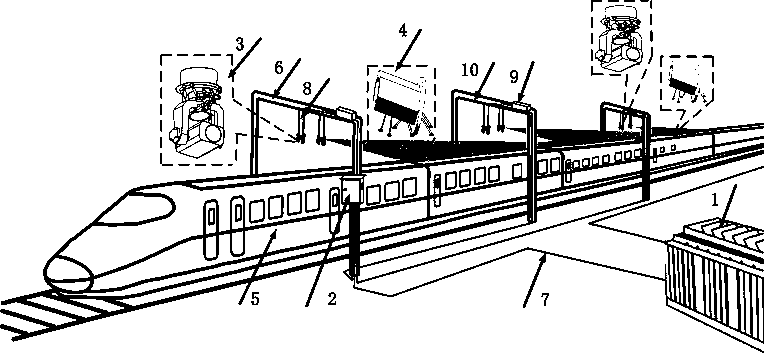
[0043] as attached figure 1 , 2 , 3, 4, 5, and 8, the rail train multi-input multi-output wireless optical communication system includes a data center 1, a vehicle-mounted network unit, a plurality of signal boxes 2, a plurality of light emitting devices 3, and a plurali...


PUM


Abstract

The invention relates to the technical field of rail train communication, in particular to a rail train multiple-input-multiple-output wireless optical communication system. The system comprises a vehicle-mounted network unit and a signal box. At least two light receiving devices are arranged on the outer side of the top of each train compartment. An optical splitter and at least two light emitting devices are arranged on a cross arm of each overhead contact system hard crossing supporting column above the rail, a signal box is arranged on any overhead contact system hard crossing supporting column in every N overhead contact system hard crossing supporting columns, and a train-mounted network unit is arranged in a train carriage. According to the invention, the light beams emitted by thetwo light emitting devices on the cross arm of the same overhead line system hard cross strut carry the same data stream; the frequency spectrum utilization rate is doubled compared with a diversity mode, the light beams emitted by the light emitting devices on the cross arms of the different overhead line system hard crossing supporting columns carry different data streams, the wavelengths are different, and the problem of interference between wireless light beams is effectively solved.

Description

technical field [0001] The invention relates to the technical field of rail train communication, and relates to a multi-input multi-output wireless optical communication system for rail trains. Background technique [0002] Existing rail train wireless communication can be realized by means of radio frequency signal communication system, optical communication system, etc., among them, the way of radio frequency signal communication is easily interfered by the signal interference of surrounding stations or residential areas and railway special signals such as GSM-R, and requires construction Large base stations require high construction and post-maintenance costs. The wireless optical communication system has wide bandwidth, low delay, and good confidentiality. It can provide high-speed communication for high-speed rail users without affecting the communication of users around the railway line. Compared with the construction cost and later maintenance costs of large base stat...

Claims


Application Information

Patent Timeline
IPC IPC(8): H04B10/11H04B10/112H04B10/50H04B10/516H04B10/66H04J14/02
CPCH04B10/11H04B10/1123H04B10/503H04B10/516H04B10/66H04J14/0202Y02D30/70
Inventor 丁举鹏陈习锋刘雯雯梅弘业郑炅赖惠成
Owner XINJIANG UNIVERSITY
Why Eureka
Try Eureka