

Compression ultrafast imaging type arbitrary reflecting surface speed interferometer
A reflective surface and interferometer technology, applied in interferometers, interference spectroscopy, instruments, etc., can solve problems such as information loss, inability to repeat multiple measurements, unfavorable strong laser pulse shaping, etc., and achieve the effect of improving imaging performance
- Summary
- Abstract
- Description
- Claims
- Application Information
AI Technical Summary
Problems solved by technology
Method used
Image

Examples
Embodiment
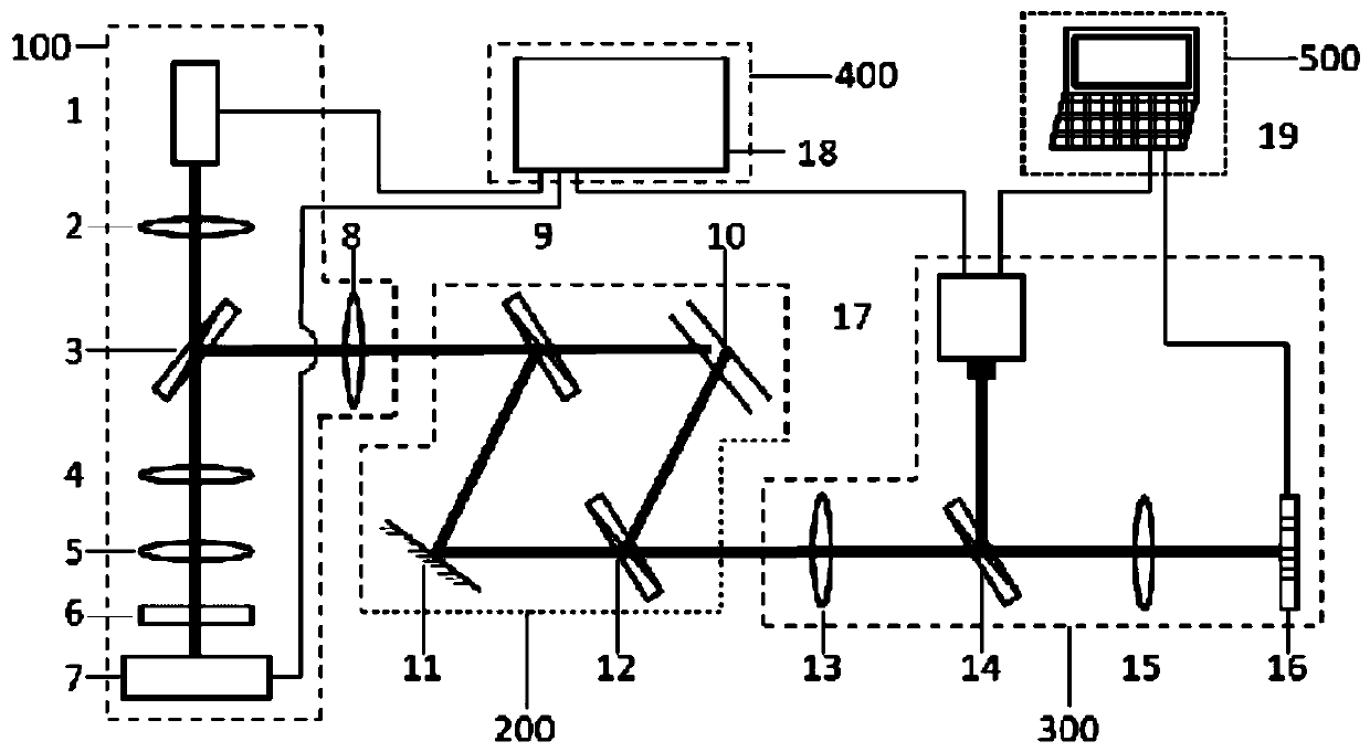
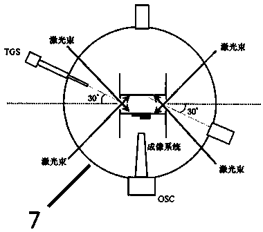
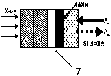
[0055] Referring to Fig. 1, Fig. 8, and Fig. 9, the nanosecond laser 1 of the light source and target system 100 of the present invention generates a probe pulse laser signal with a pulse width on the order of tens of nanoseconds, a wavelength of 532nm, and a single pulse energy greater than 1mJ. After the probe pulse laser signal is focused by the first convex lens 2, it is transmitted through the first beam splitter 3, and then imaged on the surface of the target 7 after passing through the second convex lens 4, the third convex lens 5, and the quartz glass sheet 6. Under the ablation of a beam of ultra-strong laser, the absorbed energy implodes and generates a shock wave that propagates outward. The pulsed laser probe signal focused on its surface is reflected on the shock wave front to form signal light, and passes through the quartz glass plate again. , the third convex lens 5, and the second convex lens 4 are reflected to the fourth convex lens 8 by the first beam splitte...
PUM
 Abstract
Description
Claims
Application Information