
A copper-clad steel strand production system

A production system, copper-clad steel technology, applied in the direction of cable/conductor manufacturing, electrical components, circuits, etc., can solve the problems that affect the connection effect of copper plate and steel wire, reduce the quality of copper-clad steel, and affect the welding effect, etc., to avoid The welding effect is reduced, the connection effect is good, and the tightness is improved

Active Publication Date: 2021-12-10
江苏北高电气科技有限公司
View PDF7 Cites 0 Cited by
  • Summary
  • Abstract
  • Description
  • Claims
  • Application Information

AI Technical Summary

Problems solved by technology

[0004] 1. When large machinery squeezes and covers the copper plate, there will be a gap between the copper plate and the steel wire, which will affect the connection effect between the copper plate and the steel wire, and there will be air in the gap, and the air in the gap will It will affect the welding effect during welding;
[0005] 2. After the large-scale machinery squeezes and clads the copper plate, the shape of the waste copper plate will affect the position of the welding joint during welding, making it difficult for the welding torch to align with the joint at the root of the copper plate waste, thus affecting the welding effect;
[0006] 3. After the welding of the interface after the copper covers the steel is completed, a cutter will be used to cut off the waste, and in the process of cutting off the waste, it is easy to bend the copper plate covering the steel wire, resulting in a decrease in the quality of the copper clad steel

Method used


Image

  • A copper-clad steel strand production system
  • A copper-clad steel strand production system
  • A copper-clad steel strand production system

Examples


Embodiment Construction

[0028] In order to make the technical means, creative features, goals and effects achieved by the present invention easy to understand, the present invention will be further described below in conjunction with specific illustrations. It should be noted that, in the case of no conflict, the embodiments in the present application and the features in the embodiments can be combined with each other.

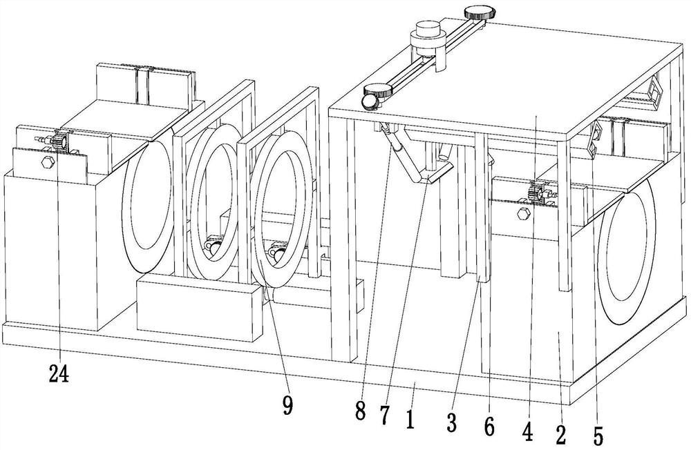
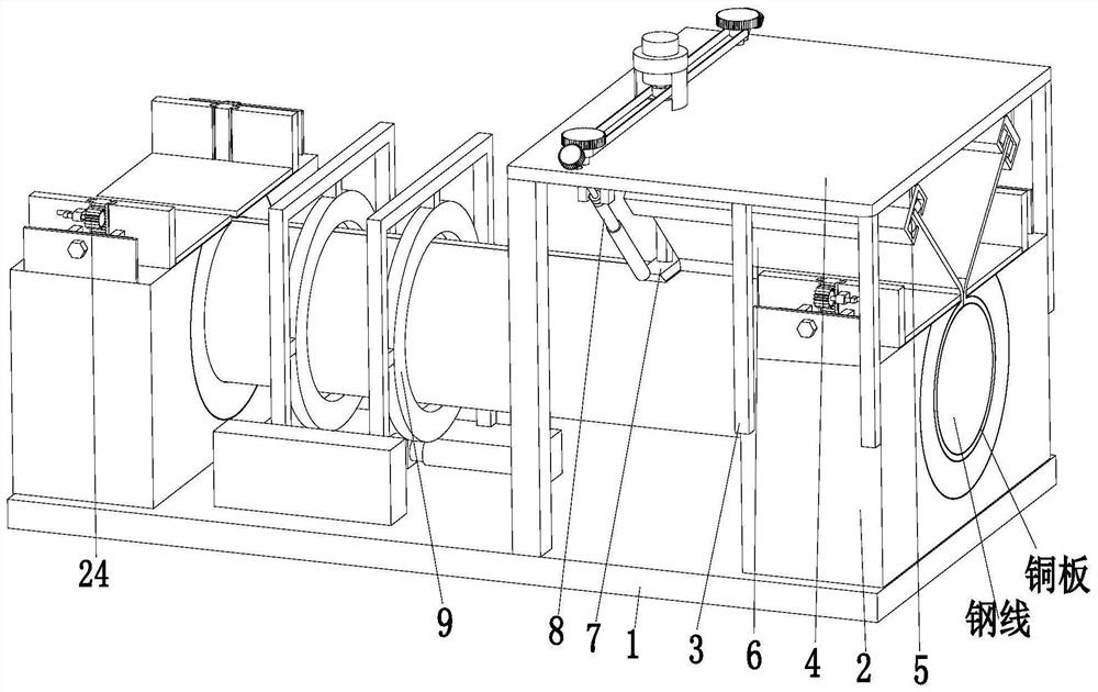
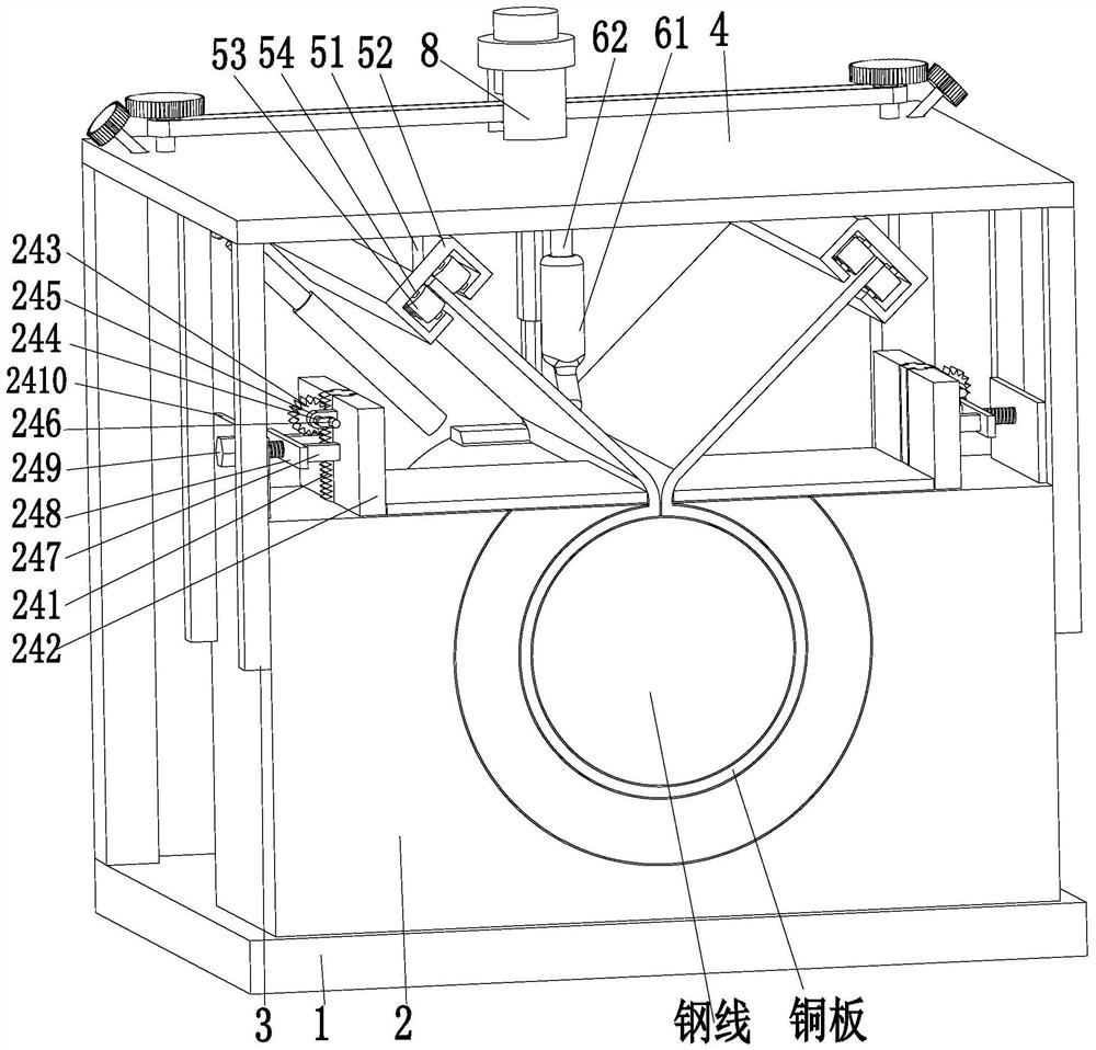
[0029] Such as Figure 1 to Figure 5 As shown, a copper-clad steel strand production system includes a base 1, a cladding mechanism 2, a support frame 3, a support plate 4, a clamping mechanism 5, an argon arc welding torch 6, a scrap cutter 7, a receiving mechanism 8 and Toggle mechanism 9, the left and right ends of the upper end surface of the base 1 are provided with a covering mechanism 2, the lower end surface of the covering mechanism 2 is installed on the upper end surface of the base 1, and is located outside the covering mechanism 2 on the right side of the upper end surfac...


PUM


Abstract

The invention relates to a copper-clad steel strand production system, which includes a base, a coating mechanism, a support frame, a support plate, a clamping mechanism, an argon arc welding torch, a scrap cutting knife, a receiving mechanism and a toggle mechanism. Both the left and right ends are provided with cladding mechanisms. A support frame is installed on the outside of the cladding mechanism on the right side of the upper end surface of the base. A support plate is installed on the top of the support frame. An argon arc welding torch is installed in the middle of the end face, a waste material cutting knife is provided on the left side of the argon arc welding torch, a material receiving mechanism is provided outside the waste material cutting knife, and a toggle mechanism is provided on the right side of the coating mechanism on the left side of the upper end surface of the base; the present invention It can solve the problems existing in the production of copper-clad steel by the cladding method: there is a gap between the clad copper plate and the steel wire, the copper plate waste affects the welding torch to align with the root of the copper plate waste, and the copper plate is easily bent after cutting off the waste, etc. .

Description

technical field [0001] The invention relates to the field of processing metal wires, in particular to a copper-clad steel strand production system. Background technique [0002] Copper-clad steel strands are widely used in high-frequency coaxial cables, electrified railways, subway light rails, railways, airports, network communications and other places for lightning protection grounding, anti-static grounding, protective grounding, grounding wires for power and petrochemical systems, etc. Compared with copper stranded wire, it has the advantages of low density, high strength and low cost. It is an updated product of traditional pure copper stranded wire. The copper-clad steel strand refers to copper-clad steel wire, that is, a composite wire wrapped with a copper layer around the steel wire. It uses the skin effect of low-voltage high-frequency signals to walk along the surface in the high-frequency area, so as long as the thickness of the copper layer reaches a certain ra...

Claims


Application Information

Patent Timeline
Patent Type & Authority Patents(China)
IPC IPC(8): H01B13/02
CPCH01B13/0207
Inventor 谈荣赋黄勤
Owner 江苏北高电气科技有限公司
Learn More