
Central liquid supply planetary polishing device and method

A polishing device and liquid supply technology, which can be used in grinding drive devices, grinding/polishing equipment, optical surface grinders, etc. Process stability and adaptability

Pending Publication Date: 2020-08-25
TIANJIN UNIV
View PDF2 Cites 6 Cited by
  • Summary
  • Abstract
  • Description
  • Claims
  • Application Information

AI Technical Summary

Problems solved by technology

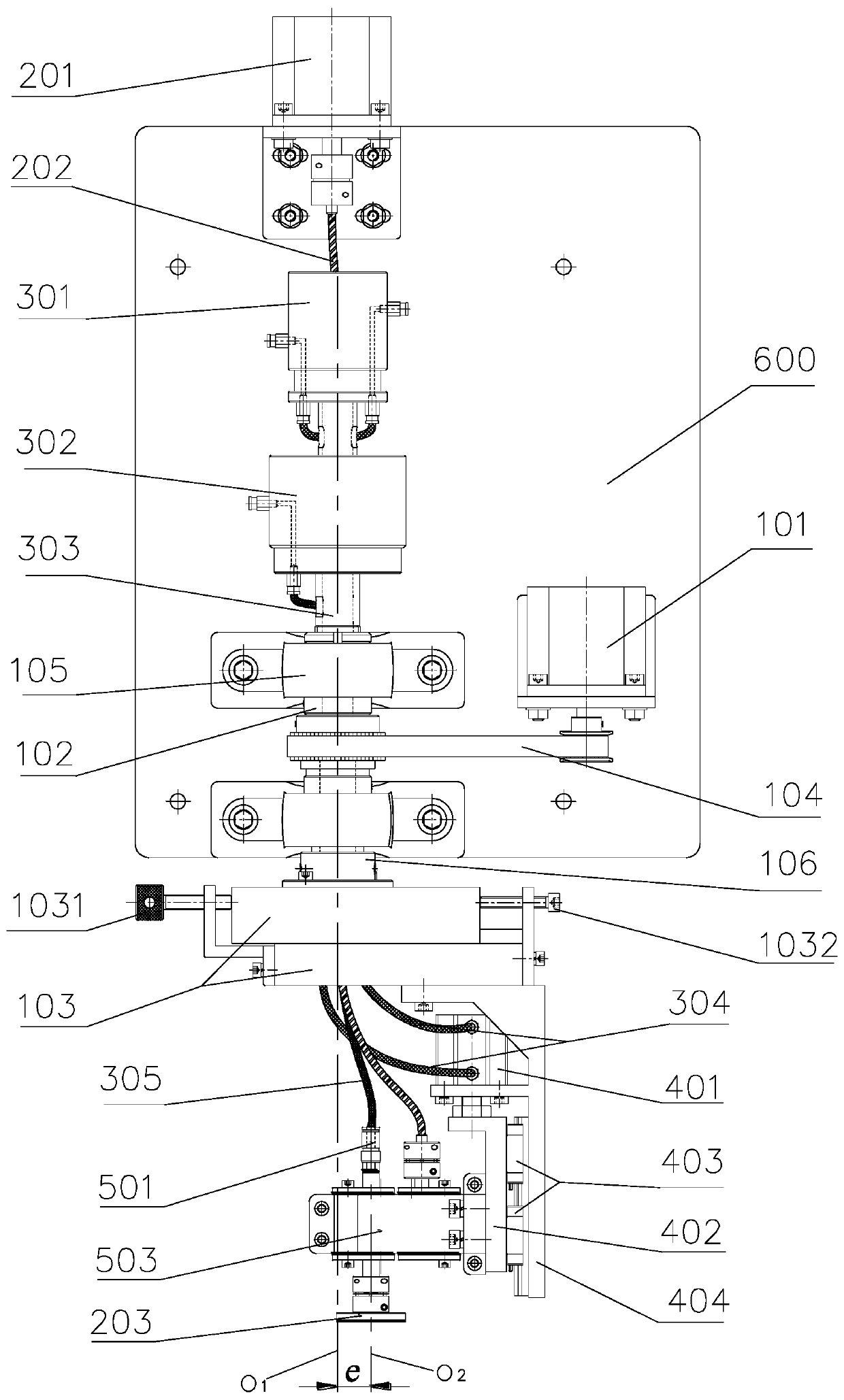
[0004] Aiming at the problems of modern large-diameter aspheric optical elements with high difficulty in ultra-precision machining, high processing cost, and low processing efficiency, this invention proposes a planetary polishing device with central liquid supply, which realizes the supply of polishing liquid from the center of the tool, and the liquid supply It is more sufficient; the revolution speed and eccentricity can be adjusted steplessly (within the allowable range), and the adjustment is convenient; the self-rotation motor does not participate in the revolution, which reduces the moment of inertia

Method used


Image

  • Central liquid supply planetary polishing device and method
  • Central liquid supply planetary polishing device and method
  • Central liquid supply planetary polishing device and method

Examples


Embodiment 1

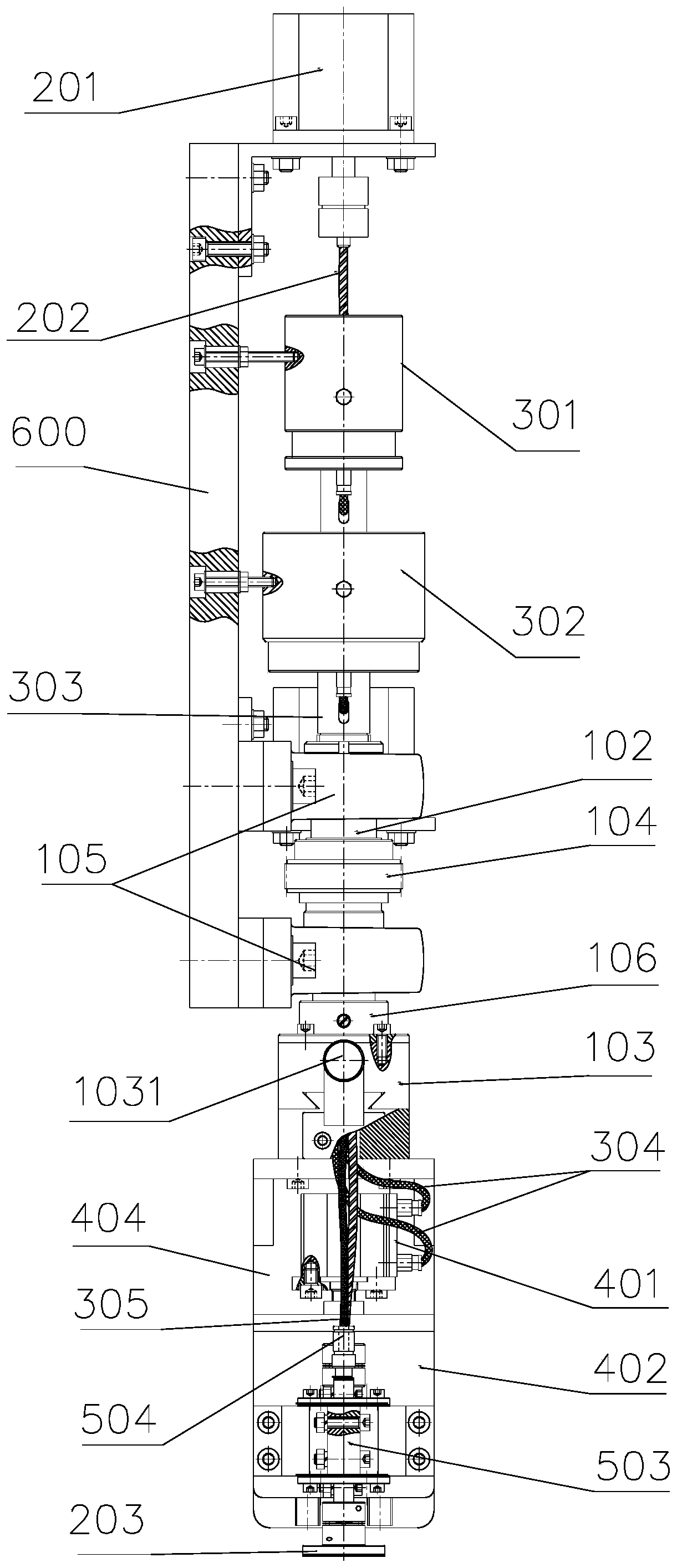
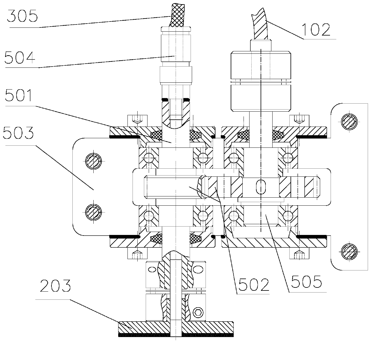
[0042] Such as figure 1 , figure 2 with image 3 As shown, in this example, the central liquid supply planetary polishing device of the present invention needs to be vertically installed on the moving shaft above the CNC machine table, the device is connected to the polishing liquid circulation system and the air pump with pipelines, and the workpiece is fixed on the on the machine table. Move the polishing disc 203 to a suitable position on the workpiece surface, use a pressure pump to pressurize the polishing solution to the working pressure, inject it from the water inlet hole of the hollow waterway rotary joint 302, and finally flow out from the center of the polishing disc 203 to the workpiece surface processing area. The air pump is used to inject compressed air at a set pressure from the air intake hole of the hollow air path rotary joint 301 and flow to the loaded thin-walled cylinder 401 to realize the loading of the polishing disc 203 on the surface of the workpie...

Embodiment 2

[0044] Such as figure 1 , figure 2 with image 3 As shown, in this example, the central liquid supply planetary polishing device of the present invention is installed at the end of the industrial robot, and the posture of the polishing disc relative to the surface of the workpiece is changed by controlling the posture of the industrial robot to adapt to the free-form surface element processing.

[0045] The device of the present invention can be installed not only on the moving shaft of ordinary numerical control machine tools, but also on the end of industrial robots, or even on a simple test bench built by oneself, which has strong versatility; by adjusting the size of the eccentricity e, an ideal The Gauss-like removal function makes the surface error converge quickly and improves the processing accuracy and efficiency; the polishing liquid is supplied from the center of the polishing disc through the hollow polishing shaft to prevent it from being thrown out due to the ...


PUM


Abstract

The invention discloses a central liquid supply planetary polishing device. The central liquid supply planetary polishing device comprises a base plate, a revolution unit, a rotation unit, a liquid and gas supply unit, a loading unit and a polishing shaft assembly. A revolution motor in the revolution unit transmits power to a hollow revolution shaft through a first-stage belt transmission pair. Aconnecting flange is arranged at one end of the hollow revolution shaft and provided with an eccentric adjusting mechanism. The rotation unit comprises a rotation motor, a transmission flexible shaftand a polishing disc. A hollow rotating shaft of the liquid and gas supply unit is connected with the other end of the hollow revolution shaft. A hollow polishing shaft in the polishing shaft assembly is connected with a liquid supply pipe in the liquid and gas supply unit and the polishing disc in the rotation unit. The revolution motor drives the eccentric adjusting mechanism to revolve aroundan axis O1. The rotation motor drives the polishing disc to rotate around an axis O2 of the polishing disc. According to the central liquid supply planetary polishing device, polishing liquid is supplied from the center of a tool, and liquid supply is more sufficient; stepless change adjustment can be achieved for the revolution and rotation speed and the eccentric distance, and adjustment is convenient; and the rotation motor does not participate in revolution, and the rotational inertia is reduced.

Description

technical field [0001] The invention relates to a planetary polishing device in the field of optical manufacturing, in particular to a central liquid supply planetary polishing device and method. Background technique [0002] With the rapid development of modern optical systems, large-aperture aspheric optical elements are widely used in laser nuclear fusion devices and large astronomical telescopes due to their high precision, light weight, good reliability and low cost compared with ordinary spherical lenses. , infrared thermal imaging, medical imaging equipment and other national defense and civilian cutting-edge technology fields, its processing technology is also developing in the direction of high precision, high efficiency and high quality. [0003] At present, the polishing technology of aspheric optical components is mainly Computer Controlled Optics Surfacing (CCOS). A large number of foreign studies have shown that the shape of the removal function is an importan...

Claims


Application Information

Patent Timeline
IPC IPC(8): B24B13/00B24B57/02B24B47/12B24B41/04B24B47/00
CPCB24B13/00B24B41/04B24B47/00B24B47/12B24B57/02
Inventor 曹中臣张军鹏林彬姜向敏
Owner TIANJIN UNIV
Learn More