Portable airplane communication navigation system detection equipment and method

A technology for testing equipment and aircraft communication. It is used in surveying, mapping and navigation, measuring devices, compasses, etc., and can solve problems such as long working hours, cumbersome daily inspections by maintenance personnel, and time-consuming and labor-intensive problems.

Pending Publication Date: 2020-08-25
AIR FORCE UNIV PLA +1
View PDF0 Cites 2 Cited by
  • Summary
  • Abstract
  • Description
  • Claims
  • Application Information

AI Technical Summary

Problems solved by technology

This makes the daily inspection of the maintenance personnel particularly cumbersome, with long working hours and low efficiency
And it is extremely inconvenient to carry so much support equipment when maneuvering around the field, and some of the simulators are also bulky, which makes the support equipment have a large tail and cannot walk
[0005] Third, there is no field inspection instrument for the radio compass at present, which makes the maintenance personnel only rely on the radio signal of the ground station or local radio station for functional inspection when inspecting the compass
Due to the shielding of the radio compass signal by the hangar and the aircraft fort, the aircraft cannot receive the compass signal
However, the self-test of the radio compass cannot fully check its function.
As a result, every time the radio compass is checked, the aircraft has to be pushed out of the hangar and the hangar, and then pushed in after the inspection, which is time-consuming and laborious, and the work efficiency is low

Method used


Image

  • Portable airplane communication navigation system detection equipment and method
  • Portable airplane communication navigation system detection equipment and method
  • Portable airplane communication navigation system detection equipment and method

Examples


Embodiment Construction

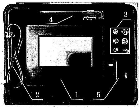
[0089] According to the working principle of the aircraft communication system and the navigation system, the present invention aims to solve the problem that the hidden faults of the communication system cannot be found in the first-line maintenance support in the field, there are many first-line maintenance support equipment for the navigation system, and the compass signal cannot be received in the hangar and the hangar. Technical problems that the compass cannot check. The portable aircraft communication and navigation system detection equipment mainly completes the following functions:

[0090] ——Detect the carrier power and carrier frequency of short-wave and ultra-short-wave radio transmitters;

[0091] ——Detect the standing wave ratio of RF feeder and antenna;

[0092] ——Detect the on and off noise sensitivity and squelch hysteresis of shortwave and ultrashortwave radio receivers;

[0093] - the insertion loss of the detection filter;

[0094] - analog compass navig...


PUM


Abstract

The invention provides portable airplane communication navigation system detection equipment. A radio frequency signal analysis assembly, a radio frequency signal generation assembly, a control assembly and the like are arranged in a body. The radio frequency signal analysis assembly comprises a standing wave analysis module, a power / frequency analysis module, a 30dB attenuator, two radio frequency input ports and a radio frequency output port. The radio frequency signal generation assembly comprises a radio frequency module, a programmable attenuator, a communication signal output port and anavigation signal output port. The control assembly comprises a main control unit, a touch display and the like. The invention further provides a detection method of the aircraft communication navigation system. The method aims to solve the technical problems that hidden faults of an external field communication system cannot be found, the number of first-line maintenance support devices of a navigation system is large, and a compass cannot be checked due to the fact that compass signals cannot be received in a machine shed and a machine fort. One-line in-situ performance detection of communication equipment such as a short-wave radio station, an ultra-short-wave radio station, a filter, a power adapter, an antenna and the like can be quickly completed, and the equipment and method are suitable for checking communication navigation equipment of various models.

Description

technical field [0001] The invention relates to a detection device and method, in particular to a portable aircraft communication and navigation detection device and method, which is mainly suitable for first-line maintenance and detection of communication and navigation equipment of civil aviation aircraft, general aviation aircraft and military aircraft. Background technique [0002] Airborne communication and navigation equipment is the central nervous system and lifeline of the aircraft. Therefore, the daily inspection of airborne communication and navigation equipment is essential in the field maintenance support. However, there are technical problems in the following aspects in the current maintenance support for airborne communication and navigation equipment. [0003] First, in the process of first-line maintenance and support, inspection methods such as maintenance self-test, voice wave correction, and single-tone self-listening are mostly used for airborne communi...

Claims


Application Information

Patent Timeline
IPC IPC(8): G01C17/38
CPCG01C17/38
Inventor 王士岩王星王连河马洪平王建程嗣怡陈游王洪迅宋光明
Owner AIR FORCE UNIV PLA
Why Eureka
Try Eureka