Flexible optical fiber, preparation method and drivable laser scalpel based on optical fiber

An optical fiber and flexible technology, applied in the field of optical fiber and its preparation, which can solve the problems of wire drawing speed limitation, difficulty in achieving high-precision surgery, and poor controllability of the thickness of the coating layer.

Inactive Publication Date: 2020-08-25
HUAZHONG UNIV OF SCI & TECH +1
View PDF19 Cites 3 Cited by
  • Summary
  • Abstract
  • Description
  • Claims
  • Application Information

AI Technical Summary

Problems solved by technology

However, there are two problems in the coating scheme: 1. Coating is a secondary processing of the drawn optical fiber. The thickness of the coating depends on the speed of the optical fiber passing through the coating cup and the viscosity of the coating material. If the coating device and the drawing device are placed On a production line, there will be certai

Method used


Image

  • Flexible optical fiber, preparation method and drivable laser scalpel based on optical fiber
  • Flexible optical fiber, preparation method and drivable laser scalpel based on optical fiber
  • Flexible optical fiber, preparation method and drivable laser scalpel based on optical fiber

Examples


preparation example Construction

[0084] The preparation method of the flexible optical fiber: comprises the following steps:

[0085] S1, preparing a preform structure of an optical fiber structure;

[0086] S2, preparing the innermost layer of the flexible reinforcement layer on the outside of the preform structure to obtain an inner layer preform;

[0087] S3, preparing at least one hollow sleeve, which is another layer in the flexible reinforcing layer, and nesting the hollow sleeve outside the inner layer preform to obtain the final optical fiber preform; the at least one hollow sleeve The material of the outermost layer has lower rigidity, and the outermost layer in the optical fiber structure, the innermost layer in the flexible reinforcing layer and at least one hollow sleeve have similar rheological properties between adjacent layers;

[0088] S4, drawing the optical fiber preform, the drawing temperature of the optical fiber preform is 60°C-600°C.

[0089] If the optical fiber structure is a step-r...

Embodiment 1

[0110] In the optical fiber in this embodiment, the central optical fiber structure is a photonic bandgap optical fiber, that is, it includes an air core at the center, and the diameter of the air core is 500 μm. The outer side of the air core is cladding, and the cladding includes a first cladding and a second cladding that are periodically and alternately stacked, and the first cladding is As 2 Se 3 Glass, ie high refractive index material, and the second cladding layer is PPSU, ie low refractive index material. The first cladding layer is located on the innermost side, and the first cladding layer and the second cladding layer are stacked alternately, each having 12 layers. The thicknesses of the first cladding layer and the second cladding layer were 1.2 μm and 2.4 μm, respectively.

[0111] The flexible reinforcement layer includes an innermost layer, which is composed of multiple layers of PPSU film. The thickness of the innermost layer is 1-20 times the thickness of ...

Embodiment 2

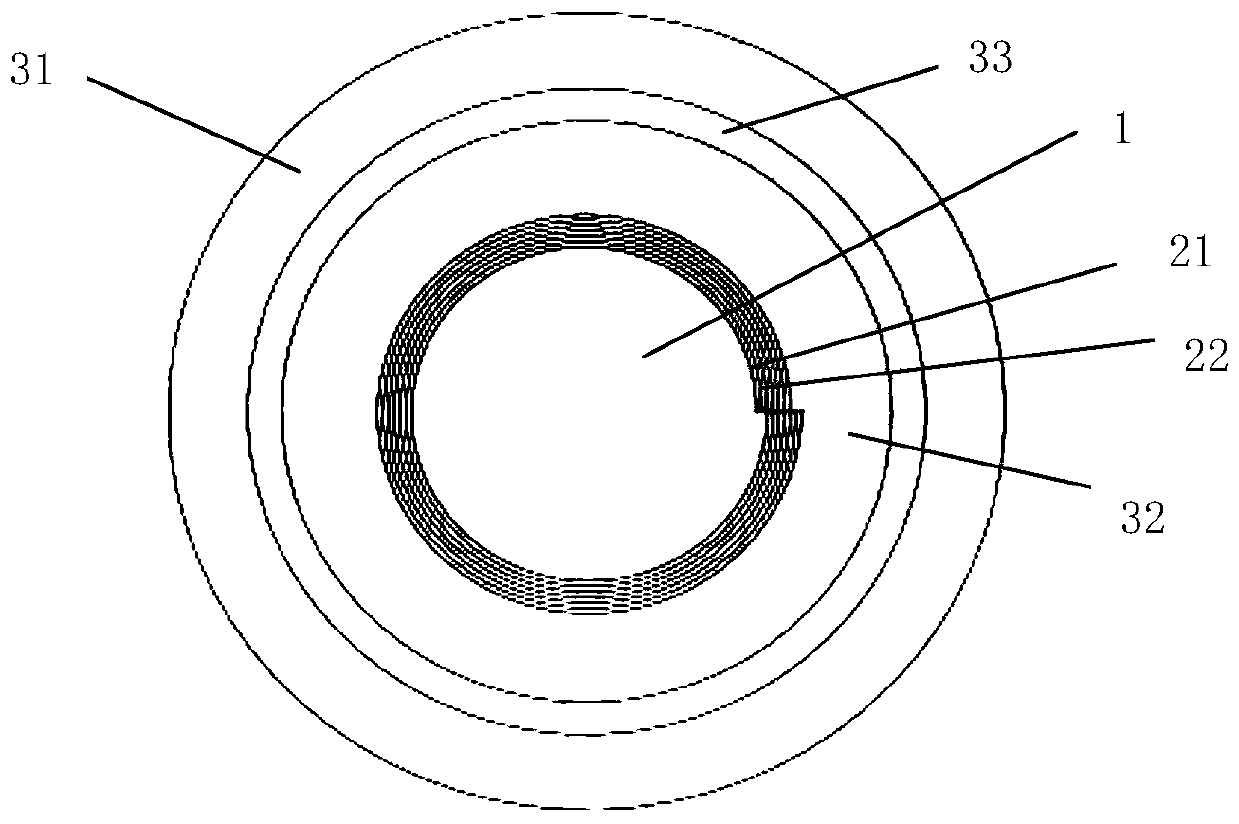
[0120] The fiber in this embodiment, as figure 1 As shown, the optical fiber structure in the center is a photonic bandgap optical fiber, and the air core 1 is in the center, and the diameter of the air core 1 is 500 μm. The outer layer of the air core 1 is a cladding, the cladding includes a first cladding 21 and a second cladding 22, the first cladding 21 is As 2 Se 3 glass, the second cladding 22 is PPSU. The first cladding layer 21 is located on the innermost side, and the first cladding layer 21 and the second cladding layer 22 are alternately stacked, 15 layers each. The thicknesses of the first cladding layer 21 and the second cladding layer 22 are 0.75 μm and 1.75 μm, respectively.

[0121] The flexibility enhancement layer comprises an innermost layer 32 which is a multilayer PPSU film. The thickness of the innermost layer 32 is 25 μm, and the outer side of the PPSU film layer is successively provided with an intermediate layer 33 and an outermost layer 31, the in...


PUM

PropertyMeasurementUnit
Thicknessaaaaaaaaaa
Diameteraaaaaaaaaa
Thicknessaaaaaaaaaa

Abstract

The invention provides a flexible optical fiber and a drivable laser scalpel based on the optical fiber. The flexible optical fiber comprise an optical fiber structure located on the inner side and aflexible enhancement layer wrapping the optical fiber structure, and the optical fiber structure has the functions of energy transmission and information transmission of a common optical fiber; the flexible enhancement layer comprises at least two layers, and the outermost layer of the flexible enhancement layer has low rigidity. According to the flexible optical fiber, through the design of the flexible enhancement layer, the bending capability of the optical fiber can be improved under the condition that the function of the optical fiber is not obviously influenced, and the selectable rangeof the outermost layer material of the optical fiber is wider. The drivable laser scalpel based on the optical fiber comprises a laser scalpel framework, the flexible optical fiber and a driving wire,the flexible optical fiber and the driving wire are located in the framework, the flexible optical fiber has the energy transmission capacity, and the driving wire is used for controlling movement ofthe framework. The drivable laser scalpel has the functions of high-power laser transmission, form sensing, posture control based on visual servo and the like.

Description

technical field [0001] The present invention relates to an optical fiber, its preparation method and its application field, in particular to a flexible optical fiber, its preparation method, and a drivable laser scalpel based on the optical fiber. Background technique [0002] With the development of medical technology, higher requirements are put forward for the precision and flexibility of the operation during the operation. For example, the previous spinal surgery with an incision size of 10cm-20cm, based on the development of the concept of minimally invasive surgery, the surgical incision can be reduced to 3cm-5cm. By reducing the wound, the patient's injury can be reduced and the patient's healing speed can be accelerated, but at the same time, higher requirements are placed on the accuracy and flexibility of surgical instruments. [0003] The development of laser technology has made laser medical treatment more and more popular in recent years. Compared with traditi...

Claims


Application Information

Patent Timeline
IPC IPC(8): G02B6/44G02B6/02C03B37/012C03B37/027A61B18/22A61B90/00A61B90/30
CPCG02B6/443G02B6/4479G02B6/02042G02B6/02328C03B37/012C03B37/027A61B18/22A61B90/30A61B90/361A61B2018/2205A61B2018/2222A61B2018/2244A61B2090/309
Inventor 陶光明杨广中高安柱任志禾
Owner HUAZHONG UNIV OF SCI & TECH
Why Eureka
Try Eureka