Capacitive touch sensing unit with neuromorphic output

A neuromorphic and tactile sensing technology, applied in the field of flexible electronic tactile sensors, can solve problems such as the limitation of the size of the tactile sensing unit array and the improvement of the tactile perception and judgment ability of the tactile sensor.

Pending Publication Date: 2020-08-25
XI AN JIAOTONG UNIV
View PDF5 Cites 3 Cited by
  • Summary
  • Abstract
  • Description
  • Claims
  • Application Information

AI Technical Summary

Problems solved by technology

However, due to factors such as limited data acquisition capabilities and control circuit computing resources, the scale of the tactile sensing unit array is greatly limited, which greatly limits the improvement of the tactile perception and judgment ability of this type of tactile sensor.

Method used


Image

  • Capacitive touch sensing unit with neuromorphic output
  • Capacitive touch sensing unit with neuromorphic output
  • Capacitive touch sensing unit with neuromorphic output

Examples


Embodiment 1

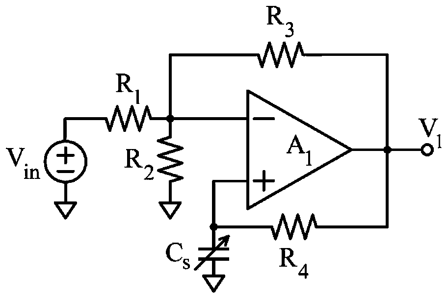
[0058] Embodiment 1, select the resistor R in the oscillator circuit 1 = R 2 = R 3 = R 4 =500KΩ, then formula (8) can be simplified as:

[0059] T=5×10 5 ln4×C s (9)

[0060] Such as Figure 5 The simulation results shown in b, at this time, if the varistor value is selected within the range of 0.002uF-0.2uF, the square wave signal output of 10HZ-1000HZ can be realized. This frequency is basically consistent with the frequency of the electrical signal of the biological nervous system, which can meet the needs of use. . And within this range, the pressure measurement sensitivity and range can achieve an ideal compromise.

Embodiment 2

[0061] Embodiment 2, select the resistor R in the oscillator circuit 1 = R 2 = R 3 = R 4 =100KΩ, then formula (8) can be simplified as:

[0062] T=10 5 ln4×C s (10)

[0063] Such as Figure 5 The simulation results shown in c, at this time, if the varistor value is selected within the range of 0.01uF-1uF, the square wave signal output of 10HZ-1000HZ can be realized. This frequency is basically consistent with the frequency of the electrical signal of the biological nervous system, which can meet the needs of use. And within this range, the pressure measurement sensitivity and range can achieve an ideal compromise.

Embodiment 3

[0064] Embodiment 3, select the resistor R in the oscillator circuit 1 = R 2 = R 3 = R 4 =10KΩ, then formula (8) can be simplified as:

[0065] T=10 4 ln4×C s (11)

[0066] Such as Figure 5 The simulation results shown in d, at this time, if the varistor value is selected within the range of 0.1uF-10uF, the square wave signal output of 10HZ-1000HZ can be realized. This frequency is basically consistent with the frequency of the electrical signal of the biological nervous system, which can meet the needs of use. And within this range, the pressure measurement sensitivity and range can achieve an ideal compromise.

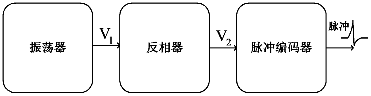
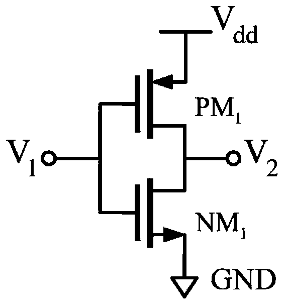
[0067] refer to image 3 As shown, the inverter is a common CMOS inverter, using a PMOS transistor PM 1 and 1 NMOS transistor NM 1 composition.

[0068] where the PMOS transistor PM 1 and 1 NMOS transistor NM 1 The gates are commonly connected with the output of the oscillator circuit; the drains are commonly connected with the input of the pulse encod...


PUM


Abstract

The invention discloses a capacitive touch sensing unit with neuromorphic output. An oscillator, an inverter and a pulse encoder are integrated in situ. When the voltage-sensitive capacitor is pressedto cause capacitance change, the oscillator generates square wave signal frequency change, the square wave signal frequency is input into the pulse encoder through the phase inverter, and the pulse encoder circuit converts a voltage signal into a pulse signal and outputs the pulse signal. The pulse encoder is controlled by a transistor output current IDS in a preceding-stage inverter and is converted into a pulse sequence with the frequency consistent with the output frequency of an oscillator in situ through a Mott memristor, a capacitor and a resistor, and therefore neuromorphic tactile information output is achieved. The neuromorphic output capacitive touch sensing unit has the characteristics of high sensitivity, low power consumption, easy integration and good biocompatibility, and has a certain application prospect.

Description

technical field [0001] The invention relates to the technical field of flexible electronic tactile sensors, in particular to a capacitive tactile sensing unit with neuromorphic output. Background technique [0002] In recent years, with the increasing maturity of artificial intelligence technology and human-computer interaction equipment based on machine learning algorithms and artificial neural networks, as an important window for mechanical devices to interact with the external environment, tactile sensing technology is used in bionic robots, medical devices, etc. All fields have important application prospects. Capacitive tactile sensors use capacitance as the sensitive parameter, which has the characteristics of high sensitivity, flexibility and stable properties, and has important application prospects and research value in the field of tactile sensing. [0003] Array integration of tactile sensing units through planar technology to obtain spatial and temporal distribu...

Claims


Application Information

Patent Timeline
IPC IPC(8): H03K17/96
CPCH03K17/962
Inventor 刘卫华苑菀彬韩传余张嘉贺贾瑞强李昕
Owner XI AN JIAOTONG UNIV
Why Eureka
Try Eureka