Gas detection system and method based on photoacoustic effect

A gas detection system and photoacoustic effect technology, applied in the direction of color/spectral characteristic measurement, measuring device, material analysis through optical means, etc., can solve the problems of limited response bandwidth of photoelectric sensors, difficult identification of spectral features, low detection sensitivity, etc. , to achieve the effect of low power consumption, high detection sensitivity and high signal-to-noise ratio

Active Publication Date: 2020-08-28
HEBEI UNIVERSITY
View PDF10 Cites 1 Cited by
  • Summary
  • Abstract
  • Description
  • Claims
  • Application Information

AI Technical Summary

Problems solved by technology

[0005] The purpose of the present invention is to provide a gas detection system and method based on the photoacoustic effect, to solve the problems of the existing devices that are difficult to identify spectral features, low detection sensitivity, long response time, and limited response bandwidth of photoelectric sensors

Method used


Image

  • Gas detection system and method based on photoacoustic effect
  • Gas detection system and method based on photoacoustic effect
  • Gas detection system and method based on photoacoustic effect

Examples


Embodiment 1

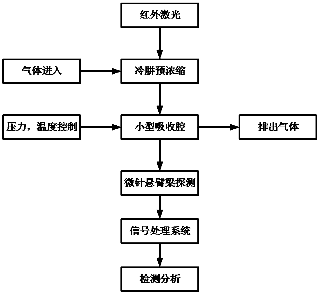
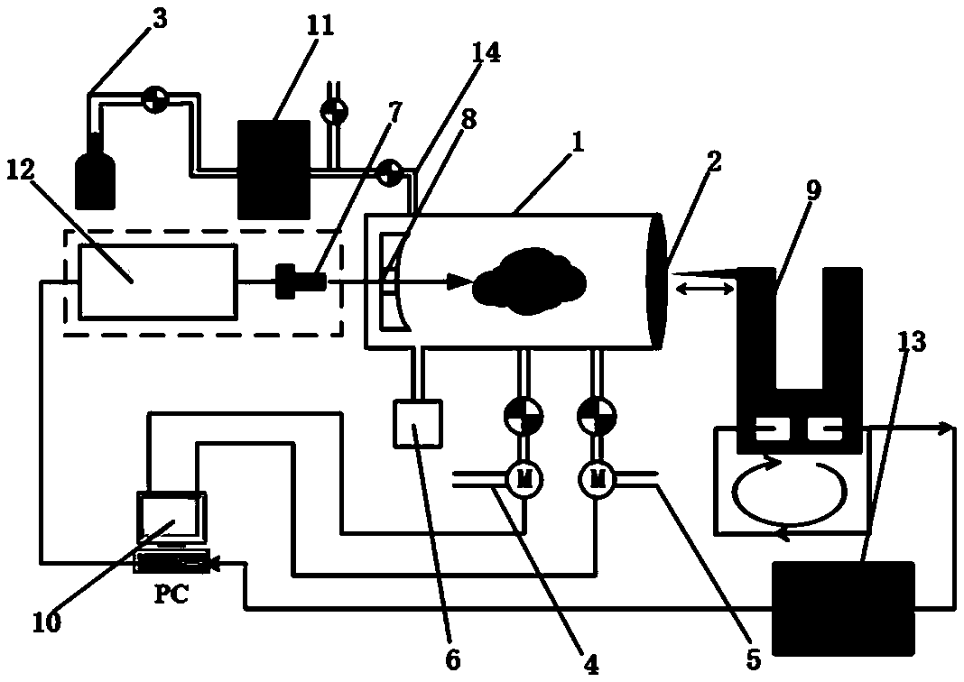
[0035] Such as figure 1 with figure 2 As shown, the gas detection system of the present invention mainly detects the gas concentration. The system first uses the gas collection device to collect the gas to be measured, and then the concentrated gas flow flows into the closed gas chamber for detection.

[0036] The specific structure includes:

[0037] The cold hydrazine pre-concentration device 11, whose internal temperature is -30°C, is used to remove the moisture in the gas to be tested 15, so as to discharge the concentrated gas molecules to be tested. The front end of the cold hydrazine pre-concentration device is provided with a gas to be tested inlet 3 , There is a filter at the inlet 3 of the gas to be tested.

[0038] A small gas absorption cavity 1 is a cuboid stainless steel cavity with a length of 4 cm, a width of 3 cm, and a thickness of 2 cm. The cavity is provided with an air inlet 14 for the gas to enter, and the air inlet is connected to the cold hydrazine ...

Embodiment 2

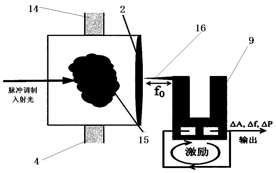
[0045] The detection process of the present invention is as follows: firstly, the one-way valve of the inlet 3 of the gas to be tested is opened, the gas to be tested flows into the cold hydrazine pre-concentration device 11, and the moisture in the gas to be tested is removed, and then the gas will enter the gas absorption chamber 1. The laser diode 7 emits a beam of collimated laser light source driven by the laser driver 12, and the wavelength of the generated laser is scanned within a certain range after being modulated. Through the microneedle cantilever beam detection system 9, the signal processing system 13 and the control system 10, the synchronous online detection of the gas concentration to be measured can be realized, and then the gas concentration can be detected and analyzed.

[0046] Among them, a gas pressure feedback control device is composed of a gas pressure sensor, a single-chip microcomputer, a relay and an air extraction system. When the air pressure in ...


PUM

PropertyMeasurementUnit
lengthaaaaaaaaaa
widthaaaaaaaaaa
heightaaaaaaaaaa

Abstract

The invention provides a gas detection system and a gas detection method based on a photoacoustic effect. The gas detection system comprises a cold hydrazine pre-concentration device, a gas absorptioncavity, a vertical cavity surface emitting laser diode, a micro-needle cantilever beam detection system, a signal processing system and a control system. According to the gas detection system, the cold hydrazine pre-concentration device is used for removing interference of moisture in a to-be-detected gas, the concentration of the to-be-detected gas is improved, after the gas absorbs light, a sound signal is excited through the photoacoustic effect, the interaction force between the gas and the surface of an absorption cavity is measured by means of a micro-needle cantilever beam tuning fork,the photoacoustic signal intensity is obtained, the gas concentration and the absorption coefficient of the to-be-detected gas for infrared light with the specific wavelength are indirectly obtained,and the gas detection system has wider response frequency band and higher detection precision and sensitivity.

Description

technical field [0001] The invention relates to the technical field of gas detection, in particular to a gas detection system and method based on the photoacoustic effect. Background technique [0002] The rapid and accurate detection of gas concentration is an indispensable key link in the fields of safety production, environmental monitoring, industrial control, etc., and has a wide range of applications in industrial production, medical and many other industries. In the field of medical and health care, the measurement of volatile organic chemicals (VOC) in human exhaled breath is a non-invasive detection technology suitable for screening for aura patients in healthy people, so it has received more and more attention. , the corresponding gas sensor research has also received great attention. [0003] At present, the current gas detection technology and method have the problem that the volume of the absorption cell is relatively large, and it is difficult to measure effec...

Claims


Application Information

Patent Timeline
Patent Type & Authority Applications(China)
IPC IPC(8): G01N21/17G01N21/39G01N21/01G01H11/08
CPCG01N21/1702G01N21/39G01N21/01G01H11/08G01N2021/1704G01N2021/391G01N2021/399G01N2201/0612Y02A50/20
Inventor 娄存广刘秀玲王鑫常超侯凯旋李喜通
Owner HEBEI UNIVERSITY
Why Eureka
Try Eureka