Full-view imaging device for pathological tissue slide

A tissue slice and imaging device technology, applied in the field of full-field imaging devices, can solve problems at the millimeter or submillimeter level, lack of resources for pathologists, inaccurate full-field images, etc.

Pending Publication Date: 2020-09-01
南京九川科学技术有限公司 +1
View PDF4 Cites 1 Cited by
  • Summary
  • Abstract
  • Description
  • Claims
  • Application Information

AI Technical Summary

Problems solved by technology

[0004] At present, the general diagnostic method of pathological tissue sections in the pathology department of the hospital is mainly based on observation under the optical microscope. Due to the existence of the lens system of the optical microscope, the field of view decreases sharply with the increase of the magnification. Therefore, most scenes The diameter of the field of view of the optical microscope is on the order of millimeters or submillimeters, which makes it impossible for the optical microscope to complete one-time imaging of tissue sections. In order to observe and compare different areas, medical staff must repeatedly move the field of view. At the same time, extremely high requirements are put forward for the richness of work experience of diagnostic medical staff, which also results in a shortage of resources for diagnostic doctors in the pathology department
[0005] Another method of automatic data collection is to install a high-precision mechanical scanning device under the microscope. After mechanical scanning, hundreds of microscopic images of a single small field of view are obtained by using software algorithms to stitch together a full field of view. Microscopic images of pathological slices, this method not only increases the cost of high-precision hardware and is time-consuming, but also causes uneven slices due to differences in the level of different slicers, resulting in changes in the clear focus of the microscope, which further leads to complete stitching Field of view image is inaccurate or out of focus
At the same time, stitching by algorithms is prone to distortion and distortion of image information at the stitching between small fields of view

Method used


Image

  • Full-view imaging device for pathological tissue slide
  • Full-view imaging device for pathological tissue slide
  • Full-view imaging device for pathological tissue slide

Examples


Embodiment 1

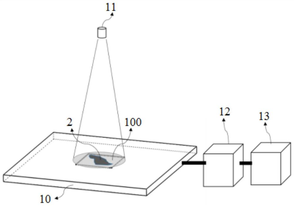
[0132] The present invention includes a full-field imaging device for pathological tissue slices, which is suitable for the imaging process of pathological tissue slices 2 in the full field of view, including:

[0133] An image sensor chip 10, a photosensitive area 100 is set in the middle of the image sensor chip 10, and the pathological tissue slice 2 is fixed directly on the surface of the photosensitive area 100, and the image sensor chip 10 is used to record the projection microscopic image data of the pathological tissue slice 2 ;

[0134] A light source device 11, which is arranged directly above the image sensor chip 10, and the light-emitting surface of the light source device 11 covers the photosensitive area 100, and the light source device 11 is used to provide illumination when imaging pathological tissue slices;

[0135] A driving device 12, the power supply end of the driving device 12 is connected to a power switch (not shown in the figure), and the output end ...

Embodiment 2

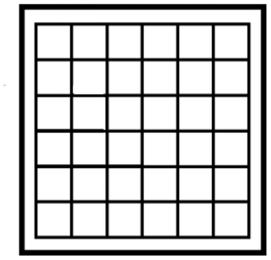
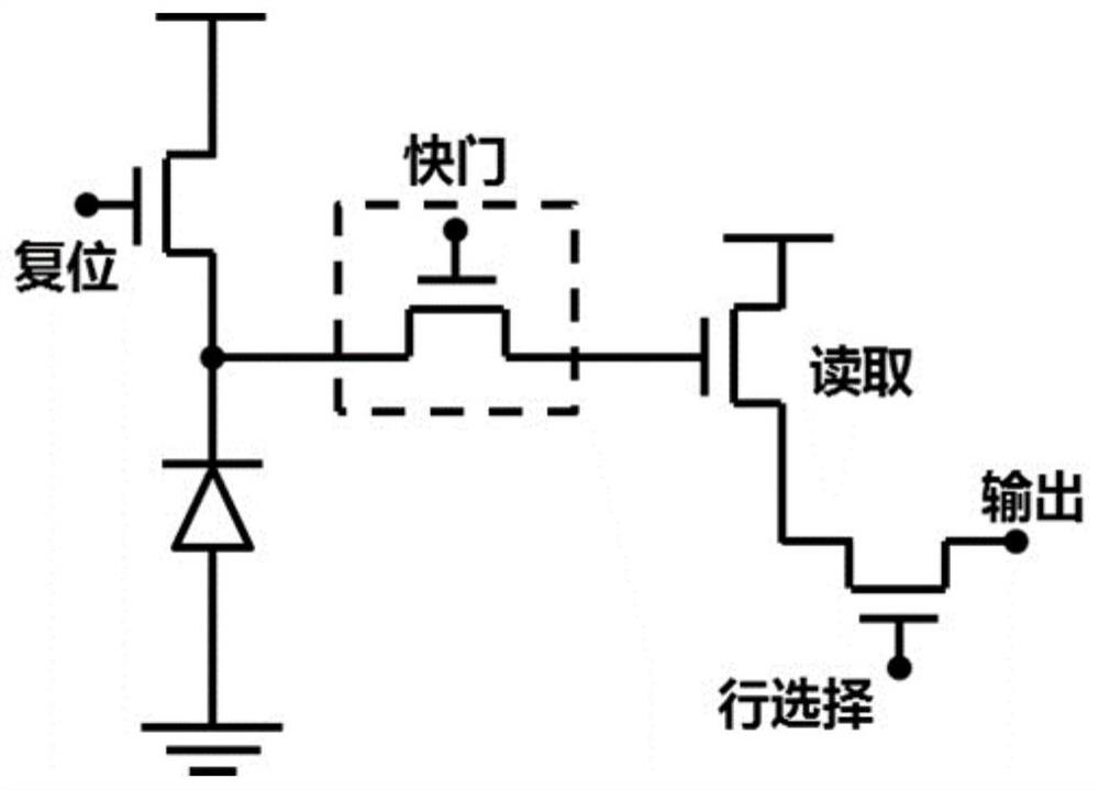
[0143] In a preferred embodiment, the detector structure of the image sensor chip 10, such as figure 2 As shown, the detector structure is composed of a large number of identical single pixel units, and the structural schematic diagram of each pixel unit is shown in image 3 As shown, wherein the size of a single pixel unit is ≤1 μm×1 μm, and the pixel scale of the image sensor chip is ≥10000×10000, for example, in this embodiment, the size of a single pixel unit can be equal to 0.5 μm×0.5 μm, the image sensor The pixel scale of the chip can be 23000×23000, thereby ensuring the coexistence of full field of view and high resolution during microscopic imaging of the pathological tissue slice.

[0144] For example, the image sensor chip 10 can be a CMOS image sensor structure, such as image 3 As shown, the image sensor chip 10 can be a semi-floating gate transistor structure, such as Figure 4 As shown, the semi-floating gate transistor structure includes a semiconductor subs...

Embodiment 3

[0152] In a preferred embodiment, in the imaging process of the pathological tissue section 2, the light source device 11 also plays a key role, wherein the light source device 11 is arranged directly above the image sensor chip 10, and between the image sensor chip 10 There is a preset vertical distance between them, for example, the preset vertical distance is set to be greater than 5 cm, and the light-emitting surface of the light source device 11 covers the photosensitive area 100, thereby providing stable illumination of approximately parallel light to achieve a full-view illumination range.

[0153] Wherein, the light source device 11 can be a red, green and blue three-color LED light source, such as Figure 11 As shown, the red, green and blue three-color LED light source contains three lamp beads of red 11-1, green 11-2, and blue 11-3 respectively, and these three lamp beads can be controlled to light up sequentially. The vertical distance between the LED light source ...


PUM

PropertyMeasurementUnit
Thicknessaaaaaaaaaa
Thicknessaaaaaaaaaa

Abstract

The invention discloses a full-view imaging device for a pathological tissue slide, and the device comprises an image sensor chip, wherein a photosensitive area is arranged in the middle of the imagesensor chip, and the pathological tissue slice is directly fixed on the surface of the photosensitive area so as to record projection microscopic image data of the pathological tissue slide; the light-emitting surface of a light source device covers the photosensitive area and is used for providing illumination during pathological tissue slide imaging; a driving device is used for respectively providing driving force for the image sensor chip and the light source device; and computer equipment is used for receiving and processing the projection microscopic image data of the pathological tissueslide. Beneficial effects are as follows: the full-view imaging device is low in structural complexity; the imaging process is simple and convenient, imaging in the full-view range can be achieved while the resolution is guaranteed, the detection efficiency of pathological tissue slide is improved, the view field range only depends on the size of a photosensitive area of the image sensor chip, and one-time full-view imaging can be conducted on the pathological tissue slide under the centimeter-level and sub-centimeter-level sizes.

Description

technical field [0001] The invention relates to the technical field of optical microscopic imaging, in particular to a full-field imaging device for pathological tissue slices. Background technique [0002] Pathological examination has been widely used in clinical work and scientific research. In clinical practice, pathological examination of cadavers and surgical pathology are mainly carried out. The purpose of surgical pathological examination is, on the one hand, to clarify the diagnosis and verify the preoperative diagnosis, and improve the level of clinical diagnosis; on the other hand, after the diagnosis is confirmed, the next treatment plan can be determined and the prognosis can be estimated, thereby improving the level of clinical treatment. Through clinical and pathological analysis, a large amount of extremely valuable scientific research data can also be obtained. [0003] Pathological slices are a type of pathological specimens. Part of the diseased tissues or...

Claims


Application Information

Patent Timeline
IPC IPC(8): G01N21/84G01N21/01G02B21/36G02B21/06
CPCG01N21/01G01N21/84G02B21/06G02B21/361G02B21/364G02B21/365
Inventor 杨程卢大骅
Owner 南京九川科学技术有限公司
Why Eureka
Try Eureka