Device with an annular spouted fluidized bed and operating method therefor

A spouted fluidized bed and equipment technology, applied in the field of its reaction chamber, can solve the problems of low heat transfer and mass transfer efficiency, and reduce interaction time

Pending Publication Date: 2020-09-11
埃姆皮瑞欧有限公司
View PDF13 Cites 2 Cited by
  • Summary
  • Abstract
  • Description
  • Claims
  • Application Information

AI Technical Summary

Problems solved by technology

The disadvantage of this device is the inefficient heat and mass transfer, as the largest particles move downward with maximum velocity near the reaction chamber wall, reducing their interaction time with the gas flow directed through the reaction chamber wall, as the fluidized particles The vertical velocity component of the spouted fluidized bed rises in the central part of the spout and falls in the periphery
Another reason for this shortcoming is that there is no jet rotation around the vertical axis of the chamber

Method used


Image

  • Device with an annular spouted fluidized bed and operating method therefor
  • Device with an annular spouted fluidized bed and operating method therefor
  • Device with an annular spouted fluidized bed and operating method therefor

Examples


Embodiment 1

[0205] Example 1 is the one covered in the most detail. The rest of the embodiments will be described in detail by the extent of their differences from the apparatus and operation of the apparatus of Embodiment 1. It is hereby meant that the general principles of operation of similar devices are known and obvious to those skilled in the art, as well as the typical set of additional devices required to carry out a particular process in a similar device.

[0206] For the sake of obviousness, not all of the following embodiments include detailed descriptions of sets of known additional devices required by the claimed device. This means that these devices are known and obvious to a person skilled in the art.

[0207] It is also meant that additional equipment listed in any of the following embodiments may also be used in any of the other embodiments, even if not mentioned in the latter, the necessity of which will be apparent to a person skilled in the art.

[0208] The followin...

specific Embodiment

[0211] Example 1.

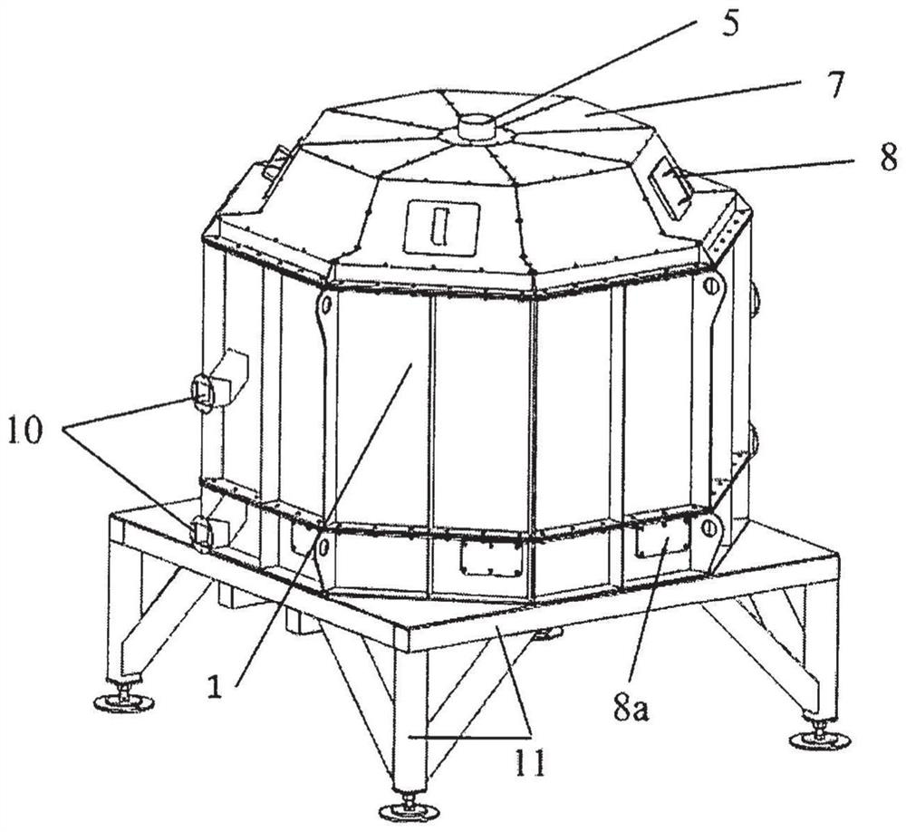
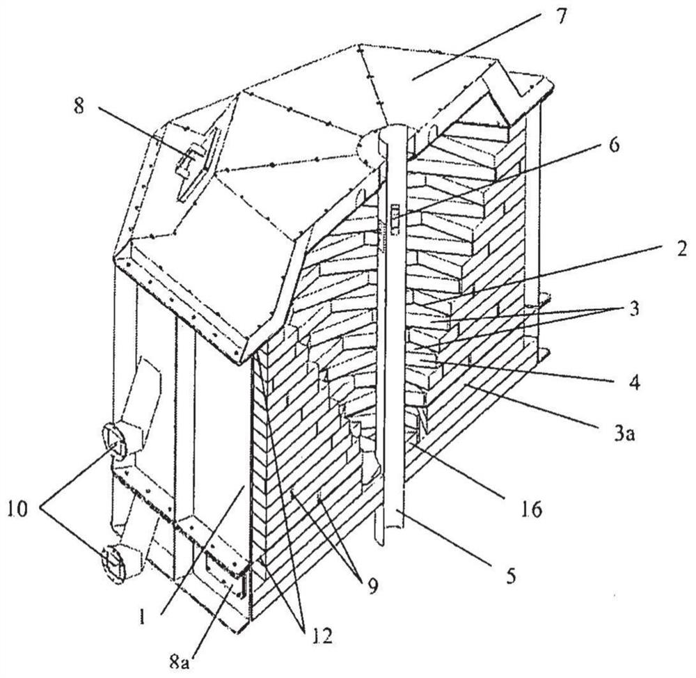
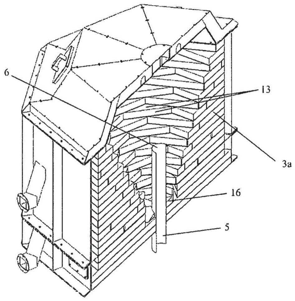
[0212] figure 1 , 1a The embodiments shown in and 2 can be used to obtain thermal energy by burning relatively large pieces of fuel, preferably of uniform composition and low bulk density, such as biofuel grains (pellets), wood chips and other similar types of fuels.

[0213] to connect to the figure 1 and 1a The list of peripherals in the equipment used to carry out the described procedure should include at least the following:

[0214] Fuel supply equipment known in the prior art to ensure an adjustable supply of fuel through one or more feed channels to the reaction chamber 2 via a flanged connection into the cover of the feed channel 8 connect;

[0215] Ignition (pilot) means known in the art, such as a pilot burner using liquid or gaseous fuel (remotely started and stopped by an automatic control system), is installed in channel 9 (leaving a gap) so that the Their channels 9 are supplied with sufficient oxidant (eg air) for operation and are co...

Embodiment 2

[0232] exist figure 1 and 1a The embodiment shown in can be used to burn finely divided or pulverized fuels such as sanding dust from furniture production, sawdust, fine peat, coal dust and other similar combustible materials. In this case, the claimed device should preferably be equipped with a lower feed mechanism for feeding the raw material (finely divided fuel). For this purpose, known feed mechanisms (eg screw feed, pneumatic conveying, etc.) are preferably mounted at the bottom of the device. For the installation of the feeding means, some channels 9 in the substructure 15 (near the bottom 17) can be utilized, or additional channels for installing (locating) the elements of the feeding mechanism should be provided in the substructure 15, through which the finely dispersed fuel passes is supplied to reaction chamber 2. Clearly, the channel 9 should have a shape and dimensions to accommodate said feed mechanism. A flange should also be located on the casing of the eq...


PUM


Abstract

A device with an annular spouted fluidized bed and an operating method therefor are claimed. The device according to the invention can be used for carrying out the majority of technical processes carried out in fluidized bed devices, inter alia for purifying gas mixtures, drying materials, pyrolysis, gasification, and combusting solid fuels such as industrial waste, agricultural waste, MSW, coal,sewage sludge, and aerobic and anaerobic digestion reactor waste, and also for carrying out other chemical reactions carried out in a fluidized bed. A reaction chamber of the present device with a rotating annular spouted fluidized bed has, throughout at least a part of its height, a downwardly tapering funnel shape with a stepped interior surface. The shape of the reaction chamber, together withthe tangential admission thereto of fluidized and other gases, makes it possible to create, in the reaction chamber, an adjustable toroidal fluidized bed, in which the rate of rotation of the particles of the material undergoing treatment can be adjusted in both the horizontal and vertical planes, and also makes it possible to control the dwell time of particles of different sizes in the reactionzone, the intensity with which materials are treated, and other process parameters.

Description

technical field [0001] The present invention relates to a plant with a rotating annular spout ebullating (fluidized) bed, in particular to its reaction chamber, which is used for carrying out various chemical reactions (technical processes), in particular for purifying gas mixtures, drying materials, pyrolysis, gasification and combustion of solid fuels (e.g. industrial waste, agricultural waste, municipal solid waste, coal, sewage sludge, aerobic and anaerobic digestion reactor waste, etc.) Other technical processes carried out in the bed. Background technique [0002] Particulate ejection in an updraft is a type of fluidization achieved in a cone or cone-shaped device. [0003] Plants with spouted fluidized beds have several advantages over other fluidized reactors. In particular, they are better suited for handling polydisperse materials and finely divided particles that are difficult to fluidize in other fluidization equipment. [0004] At the same time, equipment wit...

Claims


Application Information

Patent Timeline
Patent Type & Authority Applications(China)
IPC IPC(8): B01J8/24B01J19/24F26B17/14F23C10/02
CPCB01J8/24B01J19/24F23C10/02F26B17/14B01J8/245B01J2208/00557B01J2219/192B01J2208/00902B01J2208/00938B01J2208/00884B01J8/1818F23C10/12F23C10/24F23C2900/10007F23C10/08F26B3/082F26B25/12B01J8/386F26B17/1483
Inventor S·I·维亚切克F·N·斯托罗泽乌A·G·克瓦什宁
Owner 埃姆皮瑞欧有限公司
Why Eureka
Try Eureka