Waste gas catalytic combustion equipment for garbage disposal

A technology of catalytic combustion and waste treatment, applied in combustion methods, combustion types, lighting and heating equipment, etc., can solve the problems of water vapor recycling, incomplete waste gas treatment, waste of water resources, etc., to increase the contact area and time , the effect of accelerating catalytic combustion efficiency and accelerating incineration efficiency

Pending Publication Date: 2020-09-15
曾晓云
View PDF10 Cites 3 Cited by
  • Summary
  • Abstract
  • Description
  • Claims
  • Application Information

AI Technical Summary

Problems solved by technology

[0003] At present, when catalytic combustion equipment is used to treat exhaust gas, the catalyst is directly added to the equipment, so that the exhaust gas will not fully contact with the catalyst after entering the equipment, resulting in incomplete exhaust gas treatment, so that the exhaust gas that has not been completely treated is discharged into the In the air, it pollutes the environment. In addition, the water vapor generated by the catalytic combustion equipment is directly discharged into the air, and the water vapor is not recycled, resulting in the waste of water resources.

Method used


Image

  • Waste gas catalytic combustion equipment for garbage disposal
  • Waste gas catalytic combustion equipment for garbage disposal
  • Waste gas catalytic combustion equipment for garbage disposal

Examples


Embodiment 1

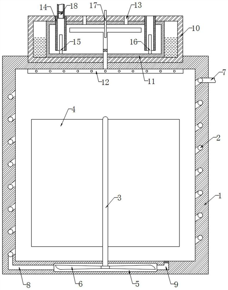
[0023] refer to figure 1 , a kind of exhaust gas catalytic combustion equipment for waste treatment, comprising a combustion chamber 1, the inner wall of the combustion chamber 1 is provided with a spiral heating chamber 2, further, the spiral setting of the spiral heating chamber 2 increases the contact area with the catalyst in the combustion chamber 1, and at the same time extends The flow time of the exhaust gas in the spiral cold spiral heating chamber 2 is shortened, and the catalyst can be preheated well. The bottom of the combustion chamber 1 is rotatably connected to the rotating shaft 3, and the side wall of the rotating shaft 3 is fixedly connected to a plurality of stirring blades 4. Combustion The lower end of the chamber 1 is provided with a circular chamber 5, the lower end of the rotating shaft 3 runs through the lower end of the combustion chamber 1 and extends into the circular chamber 5, the lower end of the rotating shaft 3 is fixedly connected with the wind...

Embodiment 2

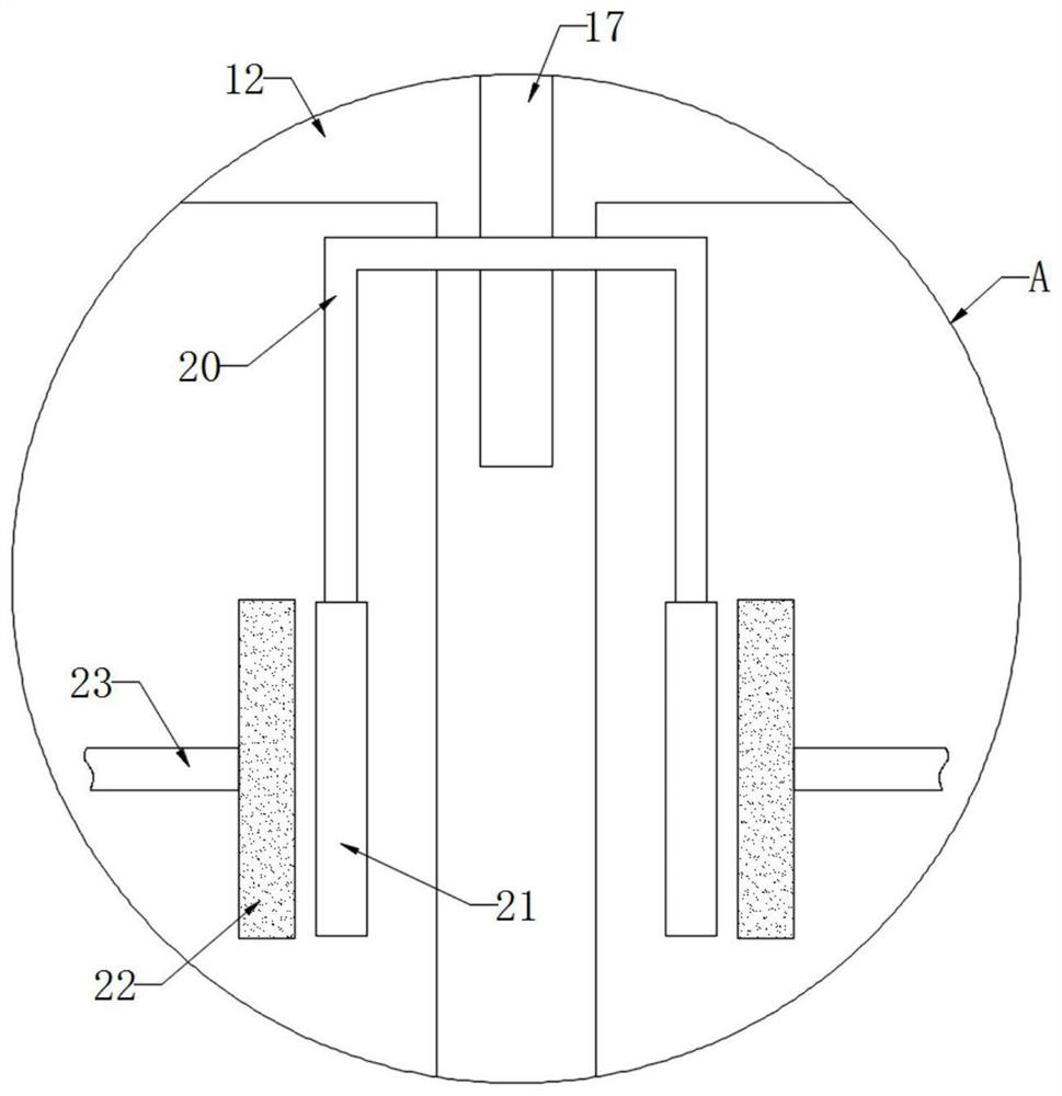
[0028] refer to Figure 2-3 , different from Embodiment 1, the one-way exhaust pipe 12 is rotationally connected with the combustion chamber 1 and the side wall of the liquid storage tank 11, the upper end of the rotating shaft 3 is fixedly connected with the lower end of the one-way exhaust pipe 12, and the inner wall of the liquid storage tank 11 is symmetrically fixed Two permanent magnets 19 are connected, and the magnetic poles of the two permanent magnets 19 facing each other are opposite, so that a magnetic field circuit is formed between the two permanent magnets 19, and then the cutting of the magnetic induction line can be realized. The one-way exhaust pipe 12 is located at Part of the side wall of the liquid storage tank 11 is plugged with a coil 20, and both ends of the coil 20 are fixedly connected with an arc-shaped piece 21, and the inner wall of the liquid storage tank 11 is symmetrically fixedly connected with a brush 22, and the arc-shaped piece 21 is attached...


PUM


Abstract

The invention discloses waste gas catalytic combustion equipment for garbage disposal. The waste gas catalytic combustion equipment comprises a combustion chamber, a spiral heating cavity is formed inthe inner wall of the combustion chamber, a rotating shaft is rotationally connected to the bottom in the combustion chamber, a plurality of stirring blades are fixedly connected to the side wall ofthe rotating shaft, a circular cavity is formed in the lower end of the combustion chamber, the lower end of the rotating shaft penetrates through the lower end of the combustion chamber and extends into the circular cavity, a wind wheel is fixedly connected to the lower end of the rotating shaft, and the side wall of the combustion chamber is connected with one end of the spiral heating cavity through an air inlet pipe. According to the waste gas catalytic combustion equipment, the wind wheel rotates to drive the stirring blades to rotate to stir a catalyst in the combustion chamber, so thatwaste gas is in full contact with the catalyst, and the waste gas is subjected to full combustion treatment; and heat contained in water vapor can enable the two ends of a temperature difference powergeneration piece to generate a large temperature difference, so that a positive electrode electrolysis rod and a negative electrode electrolysis rod are used for electrolyzing water, oxygen generatedby water electrolysis enters an incinerator, and the incineration efficiency during garbage incineration is improved.

Description

technical field [0001] The invention relates to the technical field of garbage treatment, in particular to waste gas catalytic combustion equipment for garbage treatment. Background technique [0002] Garbage incineration will produce a large amount of waste gas rich in harmful gases. In order to ensure the efficiency and environmental protection of waste gas treatment, some incinerators currently use catalytic combustion equipment to treat waste gas so that waste gas can be burned at a lower temperature. , and only produce carbon dioxide and water vapor, which are harmless to the air. [0003] At present, when catalytic combustion equipment is used to treat exhaust gas, the catalyst is directly added to the equipment, so that the exhaust gas will not fully contact with the catalyst after entering the equipment, resulting in incomplete exhaust gas treatment, so that the exhaust gas that has not been completely treated is discharged into the In the air, the environment is po...

Claims


Application Information

Patent Timeline
Patent Type & Authority Applications(China)
IPC IPC(8): F23G7/07H02N11/00
CPCF23G7/07H02N11/002F23G2202/60F23G2209/14
Inventor 曾晓云
Owner 曾晓云
Why Eureka
Try Eureka