
Shielded gate field effect transistor and method of forming the same

A field-effect transistor, shielded gate technology, applied in semiconductor devices, semiconductor/solid-state device manufacturing, electrical components, etc., to achieve the effect of ensuring device performance

Inactive Publication Date: 2020-11-20
SEMICON MFG ELECTRONICS (SHAOXING) CORP
View PDF10 Cites 0 Cited by
  • Summary
  • Abstract
  • Description
  • Claims
  • Application Information

AI Technical Summary

Problems solved by technology

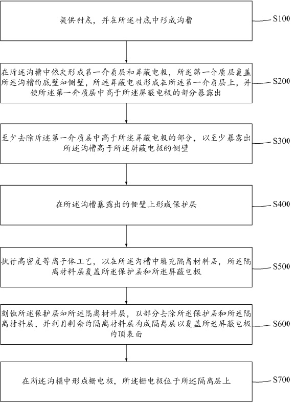
[0005] The object of the present invention is to provide a method for forming a shielded gate field-effect transistor, so as to solve the problem that plasma is easily injected into the side wall of the trench when preparing the isolation layer in the existing formation process, and improve the shape of the formed isolation layer. appearance

Method used


Image

  • Shielded gate field effect transistor and method of forming the same
  • Shielded gate field effect transistor and method of forming the same
  • Shielded gate field effect transistor and method of forming the same

Examples


Embodiment Construction

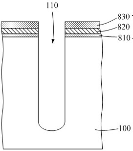
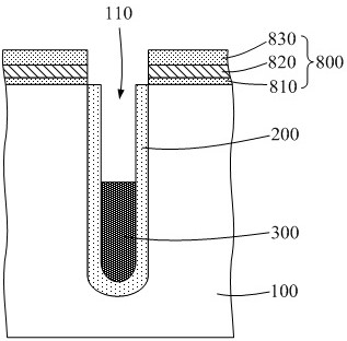
[0047] The following is attached figure 1 , Figure 2~Figure 8 The shielded gate field effect transistor proposed by the present invention and its forming method are further described in detail with specific embodiments, wherein figure 1 It is a schematic flow chart of a method for forming a shielded gate field effect transistor in an embodiment of the present invention, Figure 2~Figure 8 It is a schematic diagram of the structure of the shielded gate field effect transistor in its manufacturing process in an embodiment of the present invention. The advantages and features of the present invention will become clearer from the following description. It should be noted that all the drawings are in a very simplified form and use imprecise scales, and are only used to facilitate and clearly assist the purpose of illustrating the embodiments of the present invention.

[0048] In step S100, specifically refer to figure 2 As shown, a substrate 100 is provided, and a trench 110 ...


PUM


Abstract

The invention provides a shield gate field effect transistor and a forming method thereof. According to the forming method, a protection layer is formed on the side wall of a groove, so that the protection layer is used for preventing the side wall of the groove from being damaged by a high-density plasma process, plasma is prevented from being injected into the side wall of the groove, and the device performance of the prepared shield gate field effect transistor is guaranteed.

Description

technical field [0001] The invention relates to the technical field of semiconductors, in particular to a shielded gate field effect transistor and a forming method thereof. Background technique [0002] A shielded gate field effect transistor (Shielded Gate Trench, SGT) is more conducive to the flexible application of semiconductor integrated circuits because of its low gate-to-drain capacitance Cgd, very low on-resistance, and high withstand voltage performance. Specifically, in the shielded gate field effect transistor, by setting the shielding electrode below the gate electrode, the gate-to-drain capacitance can be greatly reduced, and the drift region of the shielded gate field effect transistor also has a relatively high impurity carrier Concentration, can provide additional benefits to the breakdown voltage of the device, which can reduce the on-resistance accordingly. [0003] Compared with other trench field effect transistors, shielded gate field effect transistor...

Claims


Application Information

Patent Timeline
Patent Type & Authority Patents(China)
IPC IPC(8): H01L21/336H01L29/78H01L29/423
CPCH01L29/4236H01L29/66734H01L29/7813
Inventor 李艳旭宋金星
Owner SEMICON MFG ELECTRONICS (SHAOXING) CORP
Learn More