Method and device for quickly separating oil and water under high temperature and high pressure

A high-temperature, high-pressure, oil-water technology, which is applied in the direction of the device whose axial direction can be reversed, the swirl device, etc., can solve the high local stress and deformation of the tangential rectangular inlet or the volute inlet, and the swirler cannot withstand relatively high pressure. High temperature and pressure loads cannot solve the problems of stress and deformation of structural components, so as to improve the flexibility of process operation, realize large-scale continuous operation, and improve the efficiency of oil-water separation

Active Publication Date: 2020-09-22
SYNFUELS CHINA TECH CO LTD
View PDF21 Cites 3 Cited by
  • Summary
  • Abstract
  • Description
  • Claims
  • Application Information

AI Technical Summary

Problems solved by technology

Patent CN104673367A discloses a step-by-step separation method of mixed oil and water coupled with oil and gas washing. The Fischer-Tropsch synthetic oil-water mixture undergoes preliminary dehydration of oil and preliminary deoiling of water in a preliminary separator, and then enters a deep dehydrator and a deep degreaser respectively. Although the method of coupling separation of two containers helps to improve the separation efficiency, it increases the equipment investment cost.
[0009] At present, the cyclone used for oil-water separation is basically a structure with a flat top plate, a tangential rectangle or a volute inlet cylinder, an overflow pipe, a large cone, a small cone and a wake tube. This structure is an efficient oil-water separation However, there are many connecting welds in each structural part, and the tangential rectangular inlet or the volute inlet will generate high local stress and deformation, which makes the cyclone unable to withstand high temperature and pressure loads; if only relying on Increasing the wall thickness of the plate and reinforcing ribs to increase the pressure and temperature bearing will greatly increase the manufacturing difficulty and production cost of the equipment, and cannot solve the stress and deformation problems of various structural components
[0010] Furthermore, the oil-water separation method described in the current patent is mainly a single process of deoiling sewage with low oil content, crude oil dehydration and purification with low water content, or oil-water pre-separation with an equivalent oil-water mass ratio, which cannot satisfy all three in one device. conditional oil-water separation

Method used


Image

  • Method and device for quickly separating oil and water under high temperature and high pressure
  • Method and device for quickly separating oil and water under high temperature and high pressure

Examples


Embodiment 1

[0071] When the amount of oil is greater than the amount of water and the oil is dehydrated:

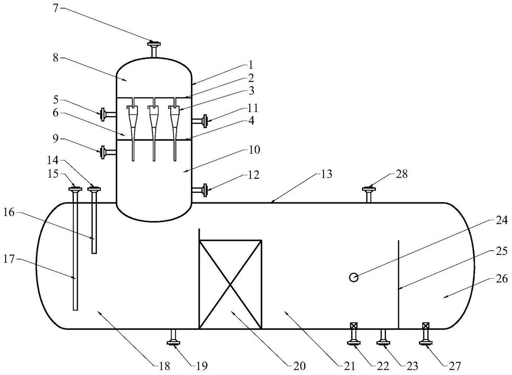
[0072] The device provided by the present invention includes an upper casing 1 and a lower casing 13. The upper casing 1 is equipped with a hydrocyclone 3 as a primary separation; the lower casing 13 is equipped with a coalescer 20 as a secondary separation. Therefore, the rapid separation of oil and water can be completed in one device.

[0073] The upstream oil-water mixture enters the feed area 6 composed of the upper shell 1, the upper partition 2, and the lower partition 4 through the mixed liquid inlet 5, and a hydrocyclone 3 is installed in the feed area 6 to adjust the split ratio of the cyclone 1 : 1 to 10, so that the overflow liquid meets the separation requirements, and the feed area 6 is provided with a sewage outlet 11 in the feed area, which can be regularly discharged.

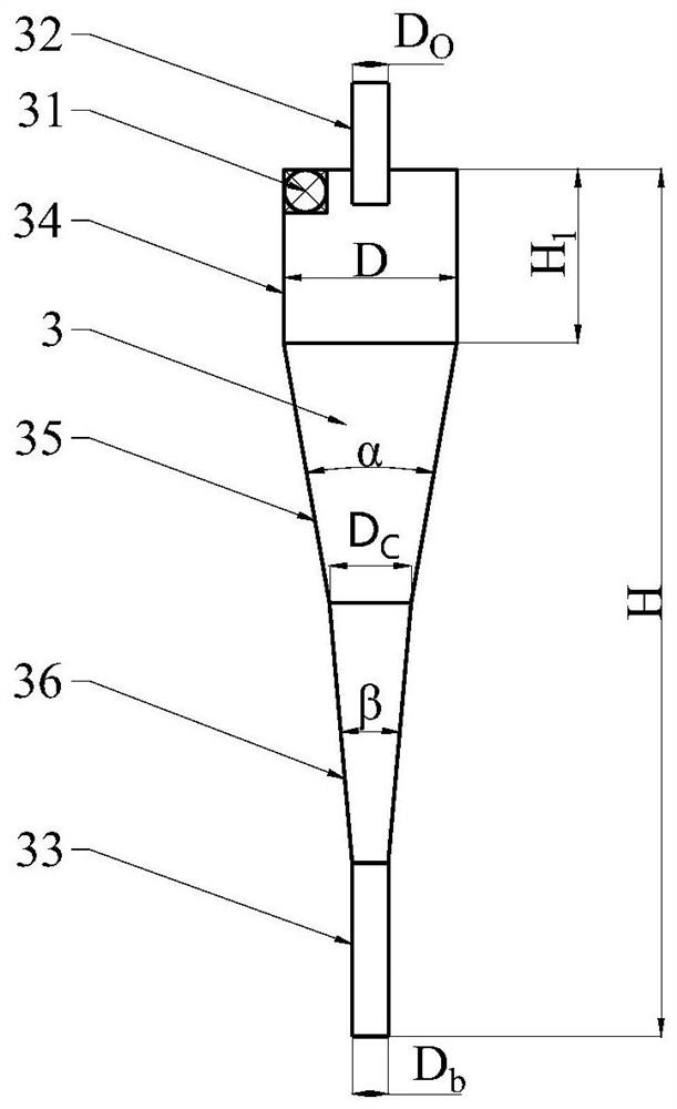
[0074] The mixed liquid in the feed zone 6 enters the feed pipe 31 of the hydrocyclone 3, and the...

Embodiment 2

[0077] When the amount of water is greater than the amount of oil, when performing water deoiling:

[0078] The device provided by the present invention includes an upper casing 1 and a lower casing 13. The upper casing 1 is equipped with a hydrocyclone 3 as a primary separation; the lower casing 13 is equipped with a coalescer 20 as a secondary separation. Therefore, the rapid separation of oil and water can be completed in one device.

[0079] The upstream oil-water mixture enters the feed area 6 composed of the upper shell 1, the upper partition 2, and the lower partition 4 through the mixed liquid inlet 5. The hydrocyclone 3 is installed in the feed area 6, and the hydrocyclone 3 is adjusted. The split ratio is 1:0.1~1, so that the underflow liquid meets the separation requirements, and the feed area 6 is provided with a sewage outlet 11 in the feed area, which can discharge sewage regularly.

[0080] The mixed liquid in the feed zone 6 enters the feed pipe 31 of the hydr...

Embodiment 3

[0083] When the quality of oil and water is the same:

[0084] The device provided by the present invention includes an upper casing 1 and a lower casing 13. The upper casing 1 is equipped with a hydrocyclone 3 as a primary separation; the lower casing 13 is equipped with a coalescer 20 as a secondary separation. Therefore, the rapid separation of oil and water can be completed in one device.

[0085] The upstream oil-water mixture enters the feed area 6 formed by the upper casing 1, the upper partition 2, and the lower partition 4 through the mixed liquid inlet 5, and a hydrocyclone 3 is installed in the feed area 6 to adjust the swirling flow. The split ratio of the device is 1:0.2~5, and the feed area 6 is provided with a sewage outlet 11 in the feed area, which can discharge sewage regularly.

[0086] The mixed liquid in the feed zone 6 enters the feed pipe 31 of the hydrocyclone 3, and the mixed liquid forms a high-speed rotating centrifugal motion in the cylindrical sec...


PUM


Abstract

The invention discloses a method and device for quickly separating oil and water under high temperature and high pressure. The device comprises an upper shell and a lower shell; a hydrocyclone is arranged in the upper shell and used for primary separation; the lower shell is provided with a coalescer for secondary separation; and an overflow liquid outlet and an underflow liquid outlet are arranged on the upper shell and can be respectively connected with an overflow liquid backflow port and an underflow liquid backflow port arranged on the top of the lower shell through pipelines. According to the method and the device, the high-temperature and high-pressure resistance of the hydrocyclone can be improved by changing the connection positions of outer interfaces of the upper shell and the lower shell according to the change of the composition of a separated medium, so that the rapid separation of oil and water in one device can be realized, and the separation efficiency can be improved.

Description

technical field [0001] The invention relates to a method and device for quick separation of oil and water under high temperature and high pressure, and belongs to the technical field of material separation. Background technique [0002] Energy is the power source of national industry, economy and social operation, and also the basis of modern human survival and social development. Indirect coal liquefaction uses coal as the raw material, converts coal into synthesis gas through gasification, water-gas shift, purification and other processes, and then converts synthesis gas into clean intermediate oil products through Fischer-Tropsch synthesis process, through fine processing of intermediate oil products , forming clean Fischer-Tropsch wax, diesel, gasoline, LPG, LNG and other products and high value-added chemicals. [0003] In the Fischer-Tropsch synthesis intermediate oil treatment process, oil-water separation is an important process of the process. For example, the hig...

Claims


Application Information

Patent Timeline
Patent Type & Authority Applications(China)
IPC IPC(8): B04C5/00B04C5/04B04C5/081B04C5/12B04C5/28B04C9/00B04C5/14B04C5/103B04C11/00
CPCB04C5/00B04C5/28B04C5/04B04C5/12B04C5/081B04C9/00B04C5/14B04C5/103B04C11/00
Inventor 张丽耿春宇贾梦磊周文贵高智雪陈彪高军虎董根全陶智超杨勇李永旺
Owner SYNFUELS CHINA TECH CO LTD
Why Eureka
Try Eureka