
New energy automobile start-stop starting battery

A new energy vehicle and start-up battery technology, which is applied to batteries, electric vehicles, lead-acid batteries, etc., can solve the problems of short life of start-stop batteries, and achieve the effects of fast discharge response, strong current capacity, and guaranteed life

Inactive Publication Date: 2020-09-25
YANCHENG INST OF TECH
View PDF0 Cites 0 Cited by
  • Summary
  • Abstract
  • Description
  • Claims
  • Application Information

AI Technical Summary

Problems solved by technology

With the development of modern science and technology, lead-acid start-stop batteries have been widely used, but compared with the existing start-stop batteries in the market, the service life is shorter. Therefore, an improved technology is urgently needed to solve this problem existing in the prior art

Method used


Image

  • New energy automobile start-stop starting battery
  • New energy automobile start-stop starting battery
  • New energy automobile start-stop starting battery

Examples


Embodiment 1

[0041] In this case, monomer B is matched with 10%, 20%, and 30% of the battery capacity of monomer A respectively. Using the blue electric test machine, Shengli VC189 plus PC terminal collects the current distribution, the recording point is 1s, and the recording time is 300s. The parallel matching of batteries occupies the percentage of current distribution respectively, see 10% matching Figure 5 , The monomer group B battery bears 100% to 38% of the current, and the monomer group A battery bears 0% to 62%. See you with 20% off Figure 6 , The monomer group B battery bears 100% to 57% of the current, and the monomer group A battery bears 0% to 43%. See you with 30% off Figure 7 , The battery group B of the single battery bears 100% to 72% of the current, and the battery group A of the single battery bears 0% to 28%. This shows that the discharge response speed of the single group B battery is fast and the current capacity is strong. It can play a role in short-term pow...

Embodiment 2

[0043] Cell B is the 10% life test of cell A capacity --- HRPSoC, the battery enters the test at 50% SoC, 2C current cycle charge and discharge, until the cut-off voltage cycle is completed, fully charged and then 50% SoC enters the test, such as Figure 8 . The pure battery group A of the single cell cannot be tested after a total of 8177 times in the 10th cycle, and the super start-stop starter battery of the battery group A in parallel with the battery group B of the single cell can still run, and the test is not continued until the 35th cycle after a total of 14979 times. Figure 9 . The principle is that when discharging for a short time, group B of the monomers, such as case 1, bears a large current. When it is left on hold for 10s, the balanced voltage of group A of the monomers will supply power to group B of the monomers. The two are voltage balanced again. From this experiment, it can be seen that the life of the monomer group B is significantly increased by 1 times...


PUM


Abstract

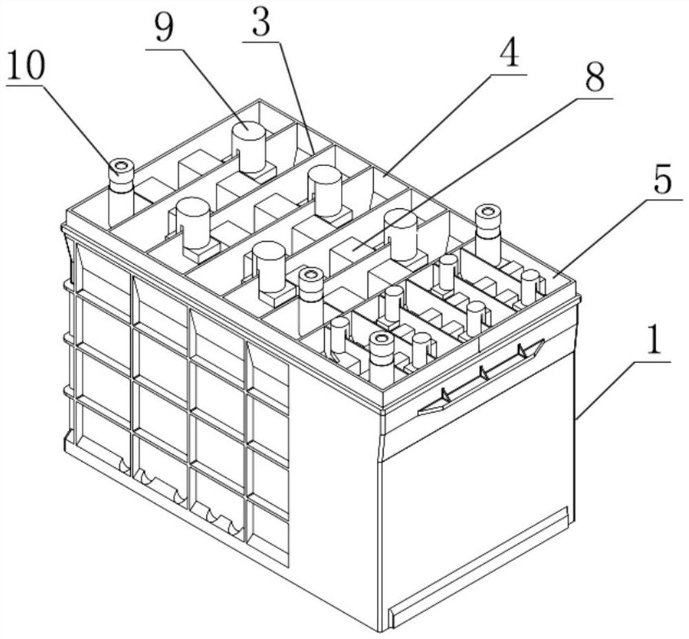
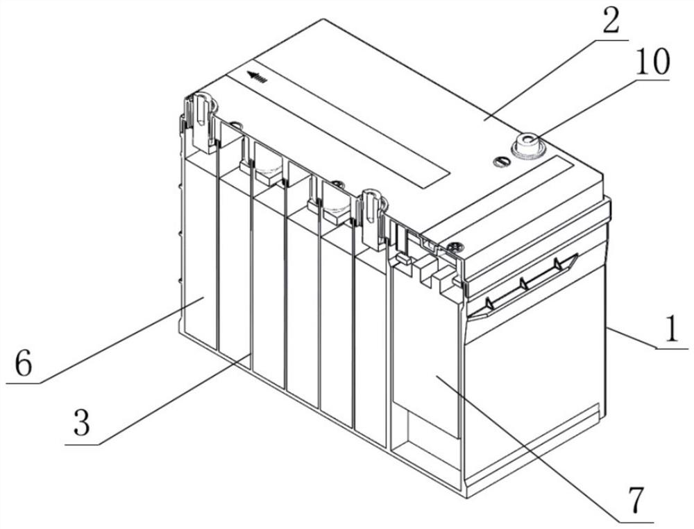
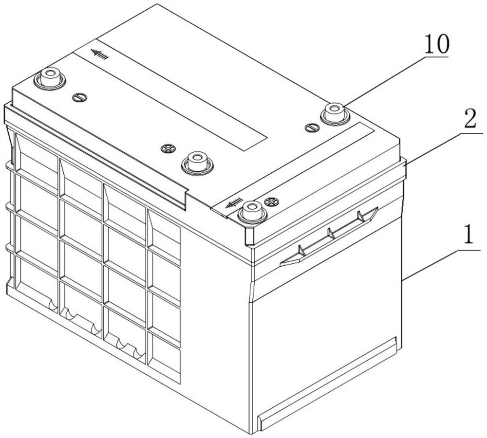
The invention discloses a new energy automobile start-stop starting battery, wherein a battery cover is arranged at the upper end of a battery shell, a plurality of monomer cavities A and monomer cavities B are respectively formed in two ends in the battery shell through diaphragms, the monomer cavity A and the monomer cavity B are vertically arranged, a plurality of monomers A and a plurality ofmonomers B are arranged, the monomers A are arranged in the monomer cavities A in a series connection manner, the monomers B are arranged in the monomer cavities B in a series connection manner, the monomers A and the monomers B are connected in parallel, busbars are arranged at the upper ends of the monomers A and the monomers B, and are fixed through a plurality of pressing columns, and two endsof the busbars are respectively connected with terminals. According to the invention, the starting-stopping battery is reasonable in structure, the internal space of the battery shell is fully utilized, the number ratio of the monomers A to the monomers B can be adapted, the discharging reaction speed of the monomer B group battery is high, the current bearing capacity is high, and the effects ofshort-time power supply, load fluctuation buffering, power output balancing, electric energy quality improving and the like can be achieved, so that the service life of the starting-stopping batteryis guaranteed.

Description

technical field [0001] The invention relates to the technical field of accumulators, in particular to a start-stop starter battery for new energy vehicles. Background technique [0002] The rise in global temperature has intensified the hazards. Governments and automobile companies have generally recognized that energy conservation and emission reduction are the main direction of automobile technology development. At present, the market mainly promotes pure electric and hybrid new energy sources. The cost of electric vehicle systems using lithium batteries and other related batteries is relatively high. Higher, the charging distance is shorter. With the development of modern science and technology, lead-acid start-stop batteries have been widely used, but compared with the existing start-stop batteries in the market, the service life is shorter. Therefore, an improved technology is urgently needed to solve this problem existing in the prior art . Contents of the invention...

Claims


Application Information

Patent Timeline
Patent Type & Authority Applications(China)
IPC IPC(8): H01M10/12B60L50/64B60R16/033
CPCB60R16/033B60L50/64H01M10/12H01M2220/20Y02E60/10Y02T10/70Y02P70/50
Inventor 蔡一正倪骁骅胡学敏石小龙陆俊张美琪
Owner YANCHENG INST OF TECH
Learn More