Lead refining and recycling system

A recovery system and furnace body technology, applied in the fields of dispersed particle filtration, gas treatment, membrane technology, etc., can solve the problems of low thermal efficiency of lead refining recovery system and ineffective utilization of flue gas waste heat.

Inactive Publication Date: 2020-09-29
重庆德能再生资源股份有限公司
View PDF8 Cites 0 Cited by
  • Summary
  • Abstract
  • Description
  • Claims
  • Application Information

AI Technical Summary

Problems solved by technology

[0006] The present invention intends to provide a lead refining recovery system to solve the problems of low

Method used


Image

  • Lead refining and recycling system
  • Lead refining and recycling system
  • Lead refining and recycling system

Examples


Embodiment 1

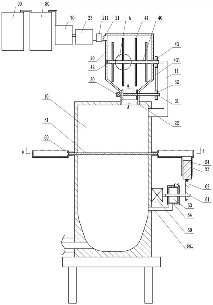
[0034] This embodiment is basically as figure 1 , figure 2 Shown: a lead refining recovery system, including a furnace body 10, a storage bin 20 and a discharge mechanism, the storage bin 20 is fixedly installed above the furnace body 10, the upper part of the storage bin 20 is connected to a recovery channel 21, and the recovery channel 21 is An air extraction mechanism is provided, and in this embodiment, the air extraction mechanism is an air extraction pump 211 . The discharge end of the recovery channel 21 is sequentially connected with a waste heat recovery mechanism, a dust removal mechanism 70 , an alkali removal mechanism and an acid removal mechanism 90 . A discharge channel 22 is connected to the lower part of the storage bin 20 , and the discharge channel 22 communicates with the upper part of the furnace body 10 .

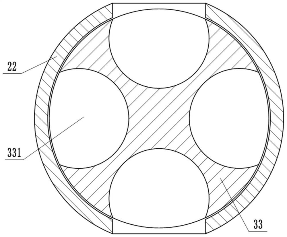
[0035] The discharge mechanism includes a motor 30 fixedly installed on the side wall of the discharge passage 22 and a discharge member rotatably ...

Embodiment 2

[0043] This embodiment limits the specific structures of the waste heat recovery mechanism, the dust removal mechanism 70 , the alkali removal mechanism and the acid removal mechanism 90 in the first embodiment. join Figure 5 As shown, in this embodiment, the waste heat recovery mechanism includes a water tank 23 , and a copper tube 231 is provided in the water tank 23 . One end of the copper tube 231 communicates with the recovery channel 21 and the other end communicates with the dust removal box 71 . After the flue gas passes into the copper tube 231, the heat of the flue gas is transferred to the water in the water tank 23 through the copper tube 231, which can make the temperature of the water rise rapidly.

[0044] The dust removal mechanism 70 includes a dust removal box 71 and a filter part arranged in the dust removal box 71 , and the filter part includes a fixed sieve plate 77 , a movable sieve plate 76 and a power component driving the movable sieve plate 76 to rec...


PUM


Abstract

The invention belongs to the technical field of secondary lead production, and particularly relates to a lead refining and recycling system which comprises a furnace body, a storage bin and a discharging mechanism. A discharging channel communicates with the upper portion of the furnace body, the discharging mechanism comprises a discharging part and a motor, and a connecting shaft is arranged atthe rotating center of the discharging part; a stirring mechanism is arranged in the storage bin and comprises a rotating shaft and a stirring shaft, a strip-shaped through groove is formed in the stirring shaft, and a plurality of through holes communicated with the strip-shaped through groove are formed in the stirring shaft; a transmission mechanism is arranged between the connecting shaft andthe rotating shaft; a flue is arranged on the furnace body, and one end of the flue extends into a cavity of the rotating shaft; a recovery channel is arranged at the upper part of the storage bin, and an air exhaust mechanism is arranged on the recovery channel; and the discharge end of the recovery channel is sequentially connected with a waste heat recovery mechanism, a dust removal mechanism,an alkali removal mechanism and an acid removal mechanism. According to the lead refining and recycling system, heat in high-temperature flue gas can be effectively recovered and utilized, and the problems that an existing lead reduction device is low in heat efficiency, and flue gas waste heat cannot be effectively utilized are solved.

Description

technical field [0001] The invention belongs to the technical field of secondary lead production, and in particular relates to a lead refining recovery system. Background technique [0002] Lead-acid batteries have stable working voltage, wide range of operating temperature and operating current, can charge and discharge hundreds of cycles, good storage performance (especially suitable for dry charging storage), and low cost, so they are widely used. With the mass production of waste lead-acid batteries, the recycling of waste lead-acid batteries is getting more and more attention. One is that the discarding of waste lead-acid batteries will cause serious pollution to the environment; the other is that due to the sharp rise in the price of lead, the recycling of lead has attracted much attention. [0003] At present, metallurgical equipment such as reverberatory furnaces, rotary kilns, and cupolas are mainly used for the smelting and recovery of lead in waste lead-acid batt...

Claims


Application Information

Patent Timeline
IPC IPC(8): C22B7/00C22B13/02C22B13/06B01D53/96B01D53/78B01D53/75B01D53/50B01D53/42B01D53/40B01D46/12B01D46/00
CPCC22B7/001C22B13/025C22B13/06B01D46/12B01D53/78B01D53/75B01D53/96B01D53/40B01D53/42B01D53/50B01D2258/0283B01D46/681B01D46/62
Inventor 伍中钢
Owner 重庆德能再生资源股份有限公司
Why Eureka
Try Eureka