
Optical module and manufacturing method thereof

A manufacturing method and optical module technology, which are applied in the field of optical communication to achieve the effects of reducing optical loss, reducing total man-hours, and improving yield

Inactive Publication Date: 2020-09-29
武汉英飞光创科技有限公司
View PDF7 Cites 1 Cited by
  • Summary
  • Abstract
  • Description
  • Claims
  • Application Information

AI Technical Summary

Problems solved by technology

[0006] The purpose of the present invention is to provide an optical module and its manufacturing method, which greatly reduces the optical loss and optical instability caused by the large-scale bending of the optical fiber, reduces the total man-hours, improves the yield rate, and solves the problem of long-term use. light problem

Method used


Image

  • Optical module and manufacturing method thereof
  • Optical module and manufacturing method thereof
  • Optical module and manufacturing method thereof

Examples


Embodiment Construction

[0028] The following will clearly and completely describe the technical solutions in the embodiments of the present invention with reference to the accompanying drawings in the embodiments of the present invention. Obviously, the described embodiments are only some, not all, embodiments of the present invention. Based on the embodiments of the present invention, all other embodiments obtained by persons of ordinary skill in the art without making creative efforts belong to the protection scope of the present invention.

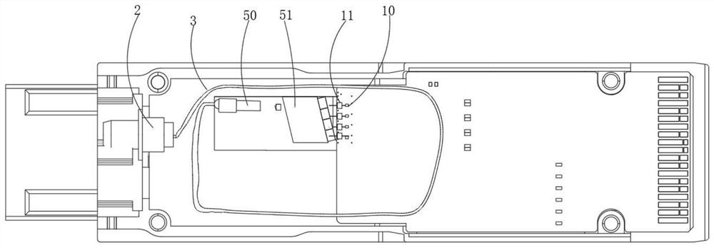
[0029] see Figure 2 to Figure 6 , the embodiment of the present invention provides an optical module, including a light emission component 1, an optical port 2, an optical fiber 3, and an optical fiber connection part 4 for guiding laser light. The laser light emitted by the light emission component 1 is sequentially connected through the optical fiber 4 and the optical fiber 3, and shoot to the optical port 2, the optical fiber 3 communicates with the optica...


PUM


Abstract

The invention relates to an optical module, which comprises a light emitting assembly, an optical port, an optical fiber and an optical fiber connecting part for guiding and sending laser. The laser emitted by the light emitting assembly sequentially passes through the optical fiber connecting part and the optical fiber and is emitted to the optical port, and the optical fiber is communicated withthe optical fiber connecting part; and a light path in the optical fiber connecting part is arranged in a downward inclined manner along the laser transmission direction. The invention discloses a manufacturing method of an optical module. The manufacturing method comprises three steps of S1-S3. According to the invention, the optical fiber connecting part is made into an inclined structure; theinclination angle of the light path in the optical fiber connecting part is controlled, so that a problem of small optical fiber bending radius is solved; further, the stress is reduced in a subsequent light path without a fiber coiling form; problems of optical fiber breakage, unattractive intersection of a plurality of internal optical fibers, possible damage to the optical fibers during assembly and the like due to fiber coiling in the module are solved, the conditions of optical loss and light instability caused by large-amplitude bending of the optical fibers are greatly reduced, the total working hours are reduced, the yield is improved, and the problem of no light after long-term use is solved.

Description

technical field [0001] The invention relates to the technical field of optical communication, in particular to an optical module and a manufacturing method thereof. Background technique [0002] With the rapid development of optical interconnection technology, the requirements for the transmission rate of communication systems are getting higher and higher, the market demand for 100G and 400G optical modules is increasing, and the requirements for cost control of optical modules are also getting higher and higher. Competition is also getting fiercer. [0003] 1X1, 1X2, 1X4, 1X8, 1X12 parallel multi-channel communication optical transmitter modules have become one of the most competitive solutions in the field of short-distance high-speed optical transmission due to their high speed and low cost. Mass production, good repeatability, small size, and good uniformity of insertion loss are the mainstream technologies for future optical communication development. [0004] Parall...

Claims


Application Information

Patent Timeline
IPC IPC(8): G02B6/42
CPCG02B6/4204G02B6/4239G02B6/424
Inventor 李波唐永正李宇
Owner 武汉英飞光创科技有限公司
Learn More