
Three-dimensional miniature endoscope

An endoscope and miniature technology, applied in the field of endoscope, can solve the problems such as hindering the use of endoscopes, large endoscopes, etc., and achieve the effects of reduced volume, large operating space, and small volume

Pending Publication Date: 2020-09-29
苏州溢博伦光电仪器有限公司
View PDF0 Cites 0 Cited by
  • Summary
  • Abstract
  • Description
  • Claims
  • Application Information

AI Technical Summary

Problems solved by technology

[0007] In order to solve the above problems, the present invention provides a three-dimensional miniature endoscope, which solves the problem that the endoscope is bulky and hinders the use of the endoscope under the premise of ensuring the efficiency of the endoscope to collect fluorescent photons

Method used


Image

  • Three-dimensional miniature endoscope
  • Three-dimensional miniature endoscope
  • Three-dimensional miniature endoscope

Examples


Embodiment 1

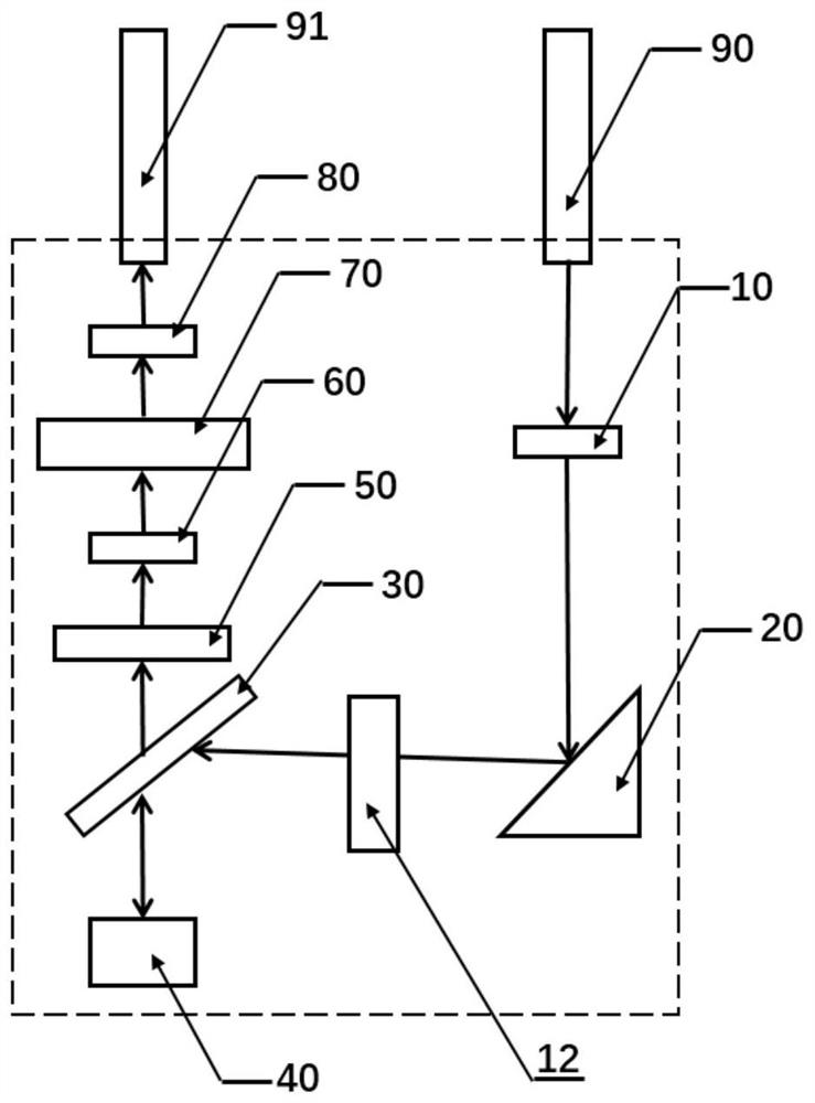
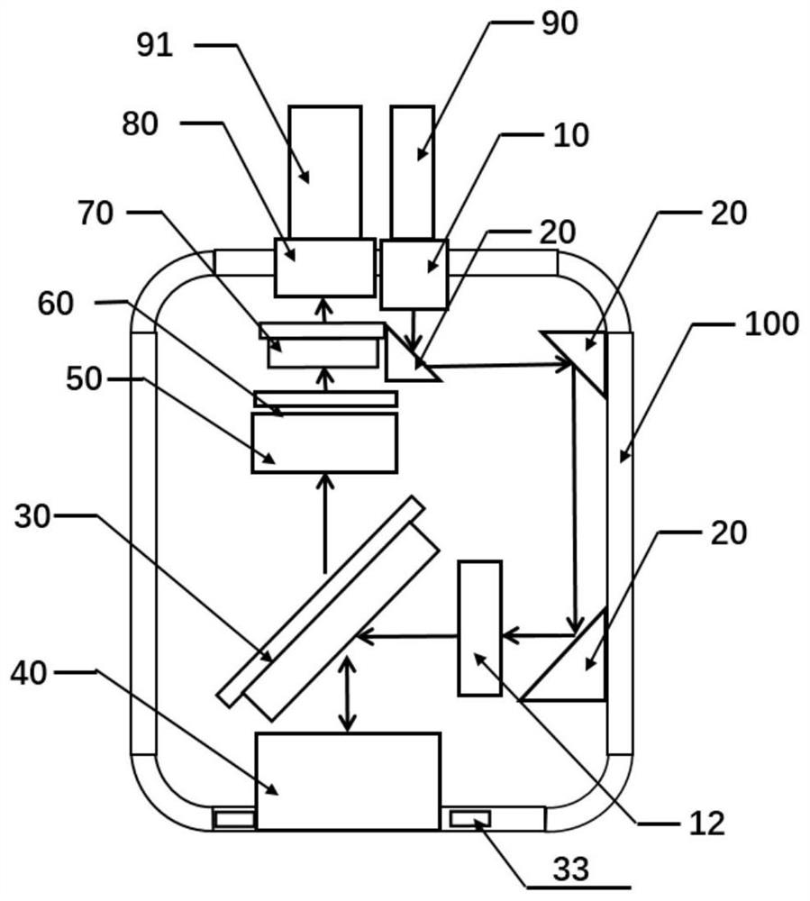
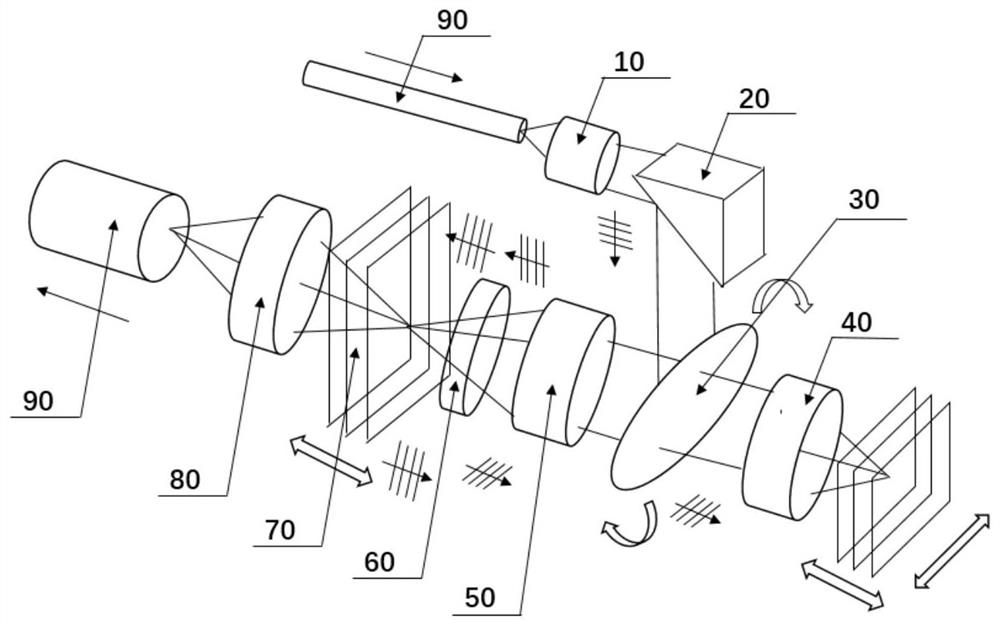
[0042] Embodiment 1 is basically as figure 1 , figure 2 and image 3 As shown in the figure, a three-dimensional miniature endoscope includes a miniature imaging probe, the miniature imaging probe is wrapped by a casing 100, and the miniature imaging probe includes in order according to the optical path: a collimating lens 10, a cylindrical lens 12, a reflecting mirror 20, a plane dichroic A mirror scanner 30, an objective lens 40, a focusing lens 50, a glass slide 60, a vertical dichroic mirror scanner 70, and a collection lens 80, wherein the objective lens 40 includes a front aperture for collecting fluorescent photons, the front aperture is vertically arranged and the lower end penetrates through the front aperture. After passing through the bottom of the housing 100, it can be directly opposite to the external sample.

[0043] The objective lens 40 is an aspherical lens, and the collimating lens 10 is used for collimating the laser light output from the laser input fib...

Embodiment 2

[0053] The difference between the second embodiment and the first embodiment is: as Image 6 As shown in the figure, the photosensitive unit of the photodetector 33 is composed of a circular array of two-dimensional pixel photoelectric sensors, such as CCD (Photo-Coupling Device) devices, CMOS (Metal Semiconductor Oxide) devices, FPA (Focal Plane Array) devices, PMT (Photoelectric A multiplier) device, a single photon counting device, or a hybrid device based on any of the above multiple photoelectric conversion principles, such as a Hamamatsu Hybrid Photodetector (HPD), a central hole or transparent material for excitation light transmitted through the objective lens 40, The annular array of two-dimensional pixel photosensors is used to receive fluorescent photons that are not received by the objective lens 40 .

Embodiment 3

[0055] The difference between the third embodiment and the first embodiment is that the filter 331, the photosensitive unit 332 and the driving unit 333 are protected by a protection element, and the protection element is made of a light-transmitting insulating material, such as optical glass. On the one hand, it can be used to isolate the external sample and the photodetector 33, and at the same time, it can also be used for electrical isolation. The protective element with a thickness of several hundreds of microns can withstand the high driving voltage of the avalanche diode, preventing the high voltage of the photosensitive unit 332 from being externally detected by personnel. cause danger.


PUM


Abstract

The invention relates to the technical field of endoscopes, and particularly relates to a three-dimensional miniature endoscope. The three-dimensional miniature endoscope comprises a miniature imagingprobe; the miniature imaging probe comprises an objective lens capable of directly facing an external sample; the objective lens is provided with a front aperture used for collecting fluorescent photons generated by the external sample; the objective lens is connected with a photoelectric detector used for collecting fluorescent photons which cannot be collected by the front aperture, and the photoelectric detector comprises an optical filter, a photoelectric sensitive unit and a driving unit which are connected in sequence; meanwhile, the three-dimensional miniature endoscope further comprises a planar dichroscope and a vertical dichroscope. According to the invention, the photoelectric detector is reasonably utilized to replace an extra optical element in the prior art; on the premise that the fluorescence photon collecting efficiency of the endoscope is guaranteed, the size of the endoscope is reduced; the problem that in the prior art, the size of a heavy endoscope is large, and consequently use of the endoscope is affected is solved; and meanwhile three-dimensional scanning of the endoscope is achieved through the planar dichroscope scanner and the vertical dichroscope scanner.

Description

technical field [0001] The invention relates to the technical field of endoscopes, in particular to a three-dimensional miniature endoscope. Background technique [0002] With the development of science and technology, medical endoscope has been widely used in the medical field. It is one of the important tools for humans to peep and treat the internal organs of the human body. In the course of more than 200 years of development, the structure of endoscope has undergone four major improvements, from the initial rigid endoscope, semi-curved endoscope to fiber endoscope, to today's electronic endoscope, Image quality has also undergone a sub-quality leap. Using LED lighting today, endoscopes can obtain color photos or color TV images. At the same time, the images are no longer ordinary images of tissues and organs, but microscopic images like those observed under a microscope, and tiny lesions can be clearly identified. According to the existing clinical experience, the smal...

Claims


Application Information

Patent Timeline
Patent Type & Authority Applications(China)
IPC IPC(8): G02B21/02G02B21/00
CPCG02B21/02G02B21/00
Inventor 不公告发明人
Owner 苏州溢博伦光电仪器有限公司
Learn More