Ultra-narrow-band navigation interference antenna design method, antenna and application thereof

A design method and ultra-narrowband technology, applied in antennas, resonant antennas, antenna arrays, etc., can solve the problems of easy-to-interference communication base station timing systems, navigation interference antennas with wide frequency domain bandwidth, interference with navigation systems in different frequency bands, etc., and achieve light weight , narrow beam characteristics, and the effect of increasing radiation efficiency

Active Publication Date: 2020-10-09
HUNAN NOVASKY ELECTRONICS TECH
View PDF9 Cites 0 Cited by
  • Summary
  • Abstract
  • Description
  • Claims
  • Application Information

AI Technical Summary

Problems solved by technology

[0003] 1. Existing navigation jamming antennas usually use a single-antenna design. It can be known from antenna theory that the radiation beam width of a single antenna is wide and the gain is low, so that the radiation energy density is poor, resulting in poor directional jamming performance of the jammer. Antenna radiation side lobes are likely to interfere with the timing system of local communication base stations, resulting in the paralysis of the communication network;
[0004] 2. With multi-unit array interference, the gain will increase accordingly, but the front-to-back ratio has not improved significantly, and the feed network at the back end of the array will become more complicated, which will increase the complexity of the system, and the cost of the array will also be corresponding The higher the value, it is not conducive to product development and production;
[0005] 3. In the low-frequency navigation frequency band, the frequency band division is complicated, and the frequency domain bandwidth of the navigation interference antenna is wide, which may easily cause interference to navigation systems in different frequency bands in the controlled area. For example, the distance between the L1 frequency band of Beidou BD2 and the L1 frequency band of GPS is less than 13MHz

Method used


Image

  • Ultra-narrow-band navigation interference antenna design method, antenna and application thereof
  • Ultra-narrow-band navigation interference antenna design method, antenna and application thereof
  • Ultra-narrow-band navigation interference antenna design method, antenna and application thereof

Examples


Embodiment Construction

[0058] The present invention will be further described below in conjunction with the accompanying drawings and specific embodiments.

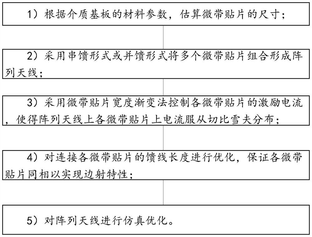
[0059] Such as figure 1 As shown, this embodiment discloses a method for designing an ultra-narrowband navigation jamming antenna, including steps:

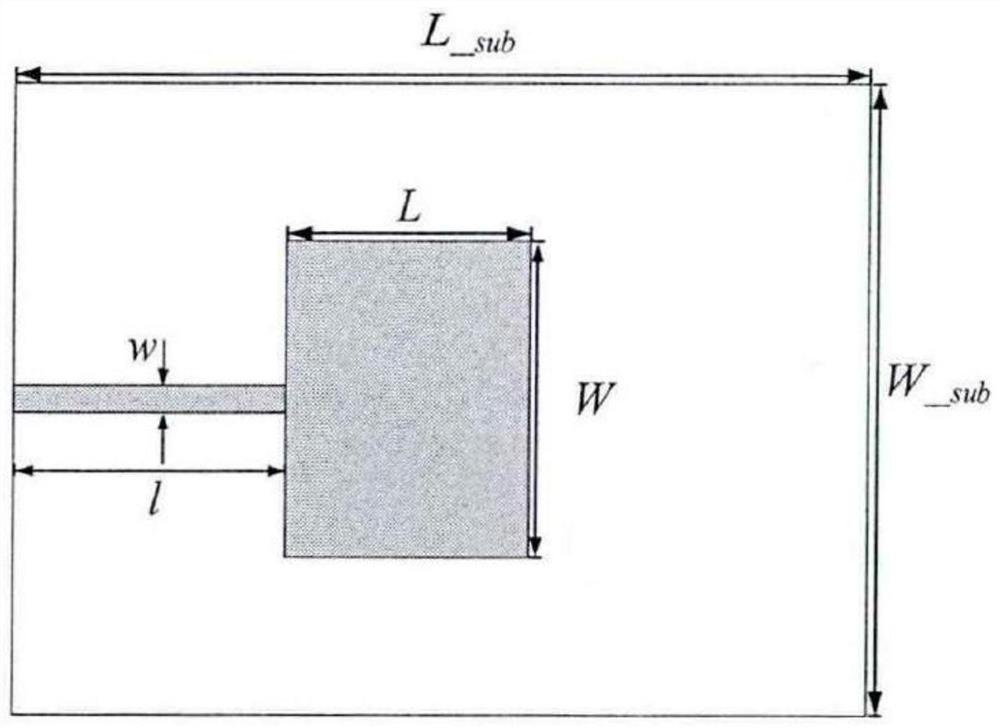
[0060] 1) Estimate the size of the microstrip patch 2 according to the material parameters of the dielectric substrate 1;

[0061] 2) Combining multiple microstrip patches 2 to form an array antenna in the form of serial feed or parallel feed;

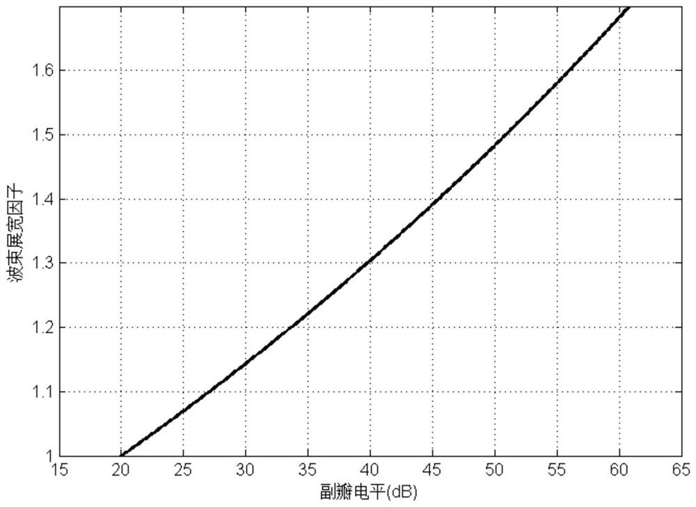
[0062] 3) The excitation current of each microstrip patch 2 is controlled by using the width gradient method of the microstrip patch 2, so that the current on each microstrip patch 2 on the array antenna obeys the Chebyshev distribution;

[0063] 4) Optimizing the length of the feeder 3 connecting each microstrip patch 2 to ensure that each microstrip patch 2 is in phase to realize the side-fire characteristic;

[0064] 5) Simulate and optimize the arra...


PUM

PropertyMeasurementUnit
electrical bandwidthaaaaaaaaaa
thicknessaaaaaaaaaa

Abstract

The invention discloses an ultra-narrow-band navigation interference antenna design method, which belongs to the technical field of interference antennas, and comprises the following steps of: 1) estimating the size of a microstrip patch according to material parameters of a dielectric substrate; 2) combining the plurality of microstrip patches to form an array antenna in a series-feed mode or a parallel-feed mode; 3) controlling the excitation current of each microstrip patch by adopting a microstrip patch width gradual change method, so that the current on each microstrip patch on the arrayantenna complies with Chebyshev distribution; 4) optimizing the length of the feeder line connected with each microstrip patch to ensure that each microstrip patch is in the same phase so as to realize the edge emission characteristic, and 5) carrying out simulation optimization on the array antenna, The method has the advantages of strong orientation capability, high energy density, small environmental influence and the like.

Description

technical field [0001] The present invention mainly relates to the technical field of jamming antennas, in particular to a design method of ultra-narrowband navigation jamming antennas, antennas and applications thereof. Background technique [0002] With the rapid iteration of UAV airborne communication systems, UAVs with self-made communication and non-cooperative inertial navigation systems will become the main threat to electronic tool warfare in the future. With the development in the direction of changing transients, the traditional "drone" jamming equipment realizes the electromagnetic suppression of the uplink of the drone, and there will be a large area of ​​"blinding". Power navigation interference equipment cannot achieve precise strikes, causing secondary damage to the environment and equipment, and has a serious impact on non-UAV inertial navigation system equipment. Therefore, the deficiencies of the existing navigation jamming antennas have the following poin...

Claims


Application Information

Patent Timeline
Patent Type & Authority Applications(China)
IPC IPC(8): G06F30/20H01Q9/04H01Q21/06H01Q1/50
CPCG06F30/20H01Q9/0407H01Q21/065H01Q1/50
Inventor 沈湘李征王生水韩明华
Owner HUNAN NOVASKY ELECTRONICS TECH
Why Eureka
Try Eureka