R-shaped open iron core and application thereof in Hall current sensor

An open iron core, Hall current technology, applied in the direction of transformer/inductor core, transformer/inductor parts, transformer/inductor coil/winding/connection, etc., can solve the reduction of magnetic flux density and sensor temperature drift , sensor output power consumption and other problems, to achieve the effect of reducing flux leakage and magnetic circuit loss, reducing built-in impedance and power consumption, and improving output drive capability

Pending Publication Date: 2020-10-09
长沙楠车电气设备有限公司
View PDF0 Cites 0 Cited by
  • Summary
  • Abstract
  • Description
  • Claims
  • Application Information

AI Technical Summary

Problems solved by technology

[0009] When the U-shaped iron core is used, the two openings face each other, so that there is a seam surface in the magnetic circuit of the iron core, and the seam surface is perpendicular to the magnetic field line, forming a broken magnetic layer, that is, the magnetic flux density of the magnetic flux in the gap is significantly reduced. , resulting in magnetic flux leakage and reluctance and uneven distribution of magnetic field
In addition, affected by the ambient temperature, the thermal expansion and contraction of the iron core will cause the size of the gap to change, resulting in the instability of the magnetic flux leakage and the temperature drift of the sensor.
[0010] 3. The magnetic cross-section of the existing iron core is rectangular, so the length of copper wire consumed by winding a coil on the iron core is relatively long, and the resistance of the coil is relatively large, resulting in large output power consumption and weak driving ability of the sensor. At the same time, it limits the matching of the subsequent control system or signal acquisition device

Method used


Image

  • R-shaped open iron core and application thereof in Hall current sensor
  • R-shaped open iron core and application thereof in Hall current sensor
  • R-shaped open iron core and application thereof in Hall current sensor

Examples


Embodiment 1

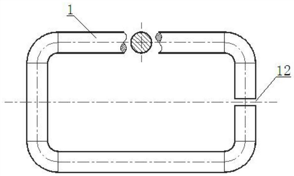
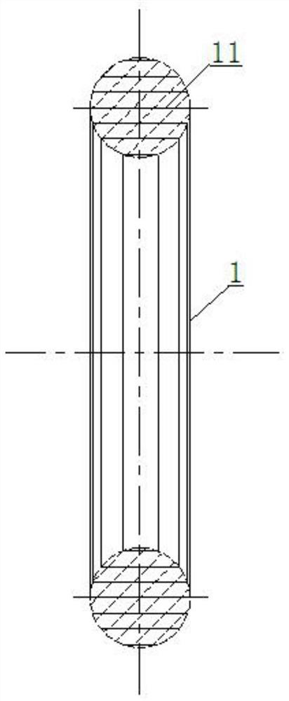
[0043] see Figure 1~4 , an R-shaped split iron core 1, specifically a square frame structure with four arc-shaped chamfered arc edges. The R-shaped open iron core 1 is formed by winding a strip-shaped metal sheet 11 from the inside to the outside, and an open air gap 12 is cut out at the side of the non-wound coil. The magnetic permeability of the iron core The cross section is circular.

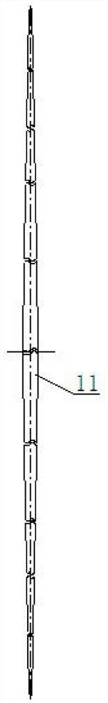
[0044] The metal sheet 11 includes a plurality of end-to-end segments, the thickness of the metal sheet 11 is equal everywhere and the width decreases from the middle to both ends step by step, the width of each part in the same segment is equal, and between adjacent segments There is a transition connection section with gradually changing width, wherein the width of the middle section is equal to the diameter of the magnetic section of the iron core, and the widths of the two sections that are symmetrical about the position of the middle section are equal, and the length of each section i...


PUM

PropertyMeasurementUnit
thicknessaaaaaaaaaa
widthaaaaaaaaaa

Abstract

The invention provides an R-shaped open iron core and application thereof in a Hall current sensor. The R-shaped open iron core is formed by winding a long-strip-shaped metal sheet from inside to outside, an opening air gap is cut in the side edge position of a non-winding coil of the iron core, and the magnetic conduction section of the iron core is round. The metal sheet comprises a plurality ofsections which are connected end to end; the thicknesses of every part of the metal sheet is the same, the width of the metal sheet gradually reduced from middle part to two ends, the width of each part in the same section is the same, a transition connecting section with gradually changed width is arranged between adjacent sections, the width of the middle section is equal to the diameter of themagnetic conductive section of the iron core, the widths of the two sections which are symmetrical about the position of the middle section are equal, and the length of each section is set to allow the section to continue complete winding for one circle on the basis of pre-winding. When the iron core is used in the Hall current sensor, the purposes of small leakage magnetic pole, low magnetic resistance, small iron loss and minimum coil internal resistance can be achieved, and thus, the accuracy and the performance of the sensor are further improved.

Description

technical field [0001] The invention relates to the technical field of Hall current sensors, in particular to an R-shaped open core and its application in Hall current sensors. Background technique [0002] The Hall current sensor is an electro-magnetic-electric conversion device based on the Hall effect and made of semiconductor materials. The Hall current sensor can realize the isolation and signal conversion between the primary side (main circuit) and the secondary side (secondary circuit), and then realize the detection and monitoring of strong current and large current in the working circuit, and output a certain ratio Relational weak current signals or other communication signals to meet the data acquisition of upper-level control and protection systems. [0003] Hall current sensors in the prior art mostly use C-shaped (ring-shaped) or U-shaped traditional iron cores, which are unsatisfactory in performance, structure and manufacturing process, mainly including the f...

Claims


Application Information

Patent Timeline
Patent Type & Authority Applications(China)
IPC IPC(8): H01F27/25H01F27/28H01F27/32H01F27/34H01F27/36G01R19/00G01R15/20
CPCG01R15/202G01R19/0092H01F27/25H01F27/2828H01F27/2885H01F27/324H01F27/325H01F27/34H01F27/341H01F27/346H01F27/36
Inventor 黄海磊刘京复彭峰
Owner 长沙楠车电气设备有限公司
Why Eureka
Try Eureka