Low-temperature storage control method for purging and dewatering of fuel cell engine

A fuel cell and low-temperature storage technology, applied in fuel cells, electrochemical generators, circuits, etc., can solve problems such as inaccurate measurement, cold start failure, and deterioration of start-up performance, and achieve the goal of improving low-temperature storage and rapid cold start performance Effect

Inactive Publication Date: 2020-10-09
HUBEI UNIV OF TECH
View PDF7 Cites 25 Cited by
  • Summary
  • Abstract
  • Description
  • Claims
  • Application Information

AI Technical Summary

Problems solved by technology

The fuel cell engine is a power generation device that integrates the stack, hydrogen supply system, air supply system, water and heat management system, and control system. It will generate a certain amount of water while generating electricity. The water contained in the membrane electrode cannot be effectively removed, and the thermal expansion and contraction of the internal material at sub-zero temperatures will lead to poor sealing of the fuel cell, and even permanent damage and cold start failure
Since the internal humidity of the fuel cell is difficult to measure accurately, if the internal moisture content is too low after purging during low-temperature storage, the cold start time will be prolonged and the start-up performance will be deteriorated (the no-load voltage is obviously low), in order to improve the safety and reliability of the fuel cell engine stability, low temperature storage and cold start performance, it is necessary to control the water content inside the fuel cell within a certain range through advanced detection and purging control methods under the premise that the humidity cannot be accurately measured, and at the same time, it will not cause excessive freezing. Dry cause the next startup performance is too low

Method used


Image

  • Low-temperature storage control method for purging and dewatering of fuel cell engine
  • Low-temperature storage control method for purging and dewatering of fuel cell engine
  • Low-temperature storage control method for purging and dewatering of fuel cell engine

Examples


Embodiment Construction

[0021] The present invention will be further described in detail below in conjunction with the accompanying drawings and specific embodiments.

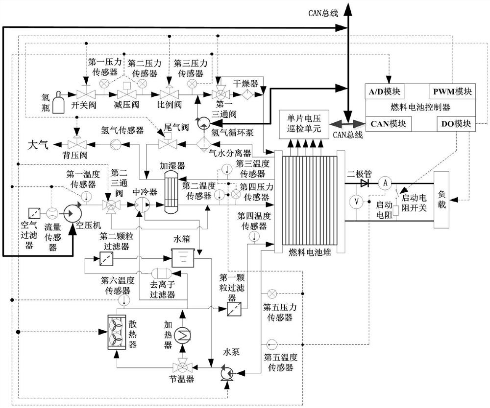
[0022] Such as figure 1 The connection structure of the fuel cell engine control system shown:

[0023] The outlet of the hydrogen bottle in the hydrogen supply system (in this case, the first three-way valve, the second three-way valve and the branch circuit are added to the existing hydrogen supply system) is sequentially connected with the on-off valve, the first pressure sensor, the pressure reducing valve, The second pressure sensor, the proportional valve, and the third pressure sensor are connected to the inlet of the first three-way solenoid valve. The first outlet of the first three-way solenoid valve is connected to the hydrogen inlet of the fuel cell stack after passing through the dryer. The first three-way The second outlet of the solenoid valve is directly connected to the hydrogen inlet of the fuel cell stack, the hydr...


PUM


Abstract

The invention relates to a low-temperature storage control method for purging and dewatering of a fuel cell engine. The low-temperature storage control method comprises the following steps of: 1) controlling load current, controlling a heater and a radiator to maintain the temperature of inlet cooling water of a fuel cell stack, controlling a rotating speed of an air compressor, and detecting thevoltage of each single cell of the fuel cell stack through a single voltage inspection unit; 2) controlling the load current by means of a fuel cell controller, controlling a heater and a radiator tomaintain the inlet cooling water temperature of the fuel cell stack, enabling air at an outlet of an air compressor to directly flow into an air inlet of the fuel cell stack without passing through anintercooler and a humidifier, controlling an inlet and outlet switching path of a first three-way valve in a hydrogen loop to enable hydrogen at an outlet of the proportional valve to directly flow into a hydrogen inlet of the fuel cell stack after passing through the dryer, and controlling the opening degree of the proportional valve to make air pressure at an inlet of the fuel cell stack to be0-20 kPa. The low-temperature storage control method does not depend on an internal resistance online test and humidity soft measurement instrument and method, and can accurately control the water content of the fuel cell engine stack.

Description

technical field [0001] The invention belongs to the technical field of fuel cell engines, and relates to a low-temperature storage control method for purging and removing water of a fuel cell engine. Background technique [0002] Due to the advantages of high energy conversion efficiency, cleanliness, no pollution, and low noise, fuel cells are the ultimate solution for automotive power systems. At present, they have become a research and development hotspot for domestic and foreign companies and research institutions, especially the "Mirai" launched by Toyota Motor. The global mass production of fuel cell vehicles has made the research and development and commercialization of fuel cell vehicles in full swing, and is currently in the initial stage of industrialization. The fuel cell engine is a power generation device that integrates the stack, hydrogen supply system, air supply system, water and heat management system, and control system. It will generate a certain amount o...

Claims


Application Information

Patent Timeline
Patent Type & Authority Applications(China)
IPC IPC(8): H01M8/04302H01M8/04303H01M8/04828H01M8/04223H01M8/04225H01M8/04228
CPCH01M8/04253H01M8/04828H01M8/04225H01M8/04228H01M8/04302H01M8/04303Y02E60/50
Inventor 全睿乐有生常雨芳黄文聪谭保华曾亮王珊珊
Owner HUBEI UNIV OF TECH
Why Eureka
Try Eureka