Preparation device and method and application of compressed nano hydrogen bubble/diesel oil mixed fuel
A technology for mixing fuels and preparation devices, which is applied in mixing methods, gas/vapor and liquid mixing, gas fuels, etc., to achieve the effects of improving fuel economy, ensuring energy security, and shortening preparation time
- Summary
- Abstract
- Description
- Claims
- Application Information
AI Technical Summary
Problems solved by technology
Method used
Image
Examples
Embodiment 1
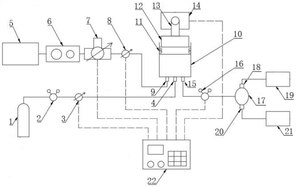
[0035] Embodiment 1: The process of preparing nano-hydrogen bubble / diesel mixed fuel using the above-mentioned compressed nano-hydrogen bubble / diesel mixed fuel preparation device of the present invention is, at first, the hydrogen pressure reducing valve 2, the gas pressure regulating solenoid valve 3, and the solenoid valve 8. The initial state of the micro-adjustment solenoid valve 16 is closed; the preparation method comprises the following steps:
[0036] In this embodiment, L=128mm; a=64mm, b=10MPa; c=5MPa.
[0037] Step 1. The predetermined compression pressure of the thrust generator 14 is selected as 10 MPa, and the thrust generator 14 is controlled by the controller 22 to push the push rod 13 to move the piston 12 to the top surface of the piston 12 and the compression cylinder 10. The distance from the bottom surface is 128mm;
[0038] Step 2. Select the inner diameter as 200mm and the volume (V 1 ) is a compression cylinder 10 of 10L, the volume V of diesel oil t...
Embodiment 2
[0045]Embodiment 2: The process of preparing nano-hydrogen bubble / diesel mixed fuel using the above-mentioned compressed nano-hydrogen bubble / diesel mixed fuel preparation device of the present invention is basically the same as the process of Example 1, the difference is only:
[0046] In this embodiment, L=200mm; a=20mm, b=5MPa; c=0.5MPa.
[0047] Step 1. The controller 22 controls the thrust generator 14 , the push rod 13 and the piston 12 to move until the distance between the top surface of the piston 12 and the bottom surface of the compression cylinder 10 is L=200 mm.
[0048] Step 2: Change the inner diameter of the compression cylinder 10 from 200mm to 300mm, change V 1 From 10L to 8L, V 3 Changed from 2L to 1L, the diesel flow rate h of the flow controller 7 was changed from 1L / min to 0.25L / min, the movement speed of the bottom surface of the piston 12 was changed from 32mm / min to 3.5mm / min, and the solenoid valve 8 was changed from open to closed The time interval...
Embodiment 3
[0052] Embodiment 3: The process of preparing nano-hydrogen bubbles / diesel mixed fuel using the above-mentioned compressed nano-hydrogen bubbles / diesel mixed fuel preparation device of the present invention is basically the same as the process of Example 1, the difference is only:
[0053] In this embodiment, L=120mm; a=30mm, b=8MPa; c=2MPa.
[0054] Step 1. The controller 22 controls the thrust generator 14 , the push rod 13 and the piston 12 to move until the distance between the top surface of the piston 12 and the bottom surface of the compression cylinder 10 is 120 mm.
[0055] Step 2, change the inner diameter of the compression cylinder 10 from 200mm to 400mm, change V 1 From 10L to 15L, V 3 Changed from 2L to 3L, the diesel flow rate h of the flow controller 7 was changed from 1L / min to 0.5L / min, the movement speed of the bottom surface of the piston 12 was changed from 32mm / min to 4mm / min, and the time from opening to closing of the solenoid valve 8 The interval d i...
PUM
| Property | Measurement | Unit |
|---|---|---|
| The inside diameter of | aaaaa | aaaaa |
Abstract
Description
Claims
Application Information
 - R&D Engineer
- R&D Manager
- IP Professional
- Industry Leading Data Capabilities
- Powerful AI technology
- Patent DNA Extraction
Browse by: Latest US Patents, China's latest patents, Technical Efficacy Thesaurus, Application Domain, Technology Topic, Popular Technical Reports.
© 2024 PatSnap. All rights reserved.Legal|Privacy policy|Modern Slavery Act Transparency Statement|Sitemap|About US| Contact US: help@patsnap.com


