A slurry device for preparing bio-organic water fertilizer and its preparation method
An organic and water-fertilizer technology, which is applied in the preparation of bio-organic water and fertilizer slurry equipment and its preparation field, can solve the problems of large differences in crop growth and development, damage to the balance of soil fertility, and reduce organic water and fertilizer fertility. The effect of speeding up the crushing speed and improving the fineness
- Summary
- Abstract
- Description
- Claims
- Application Information
AI Technical Summary
Problems solved by technology
Method used
Image
Examples
Embodiment 1
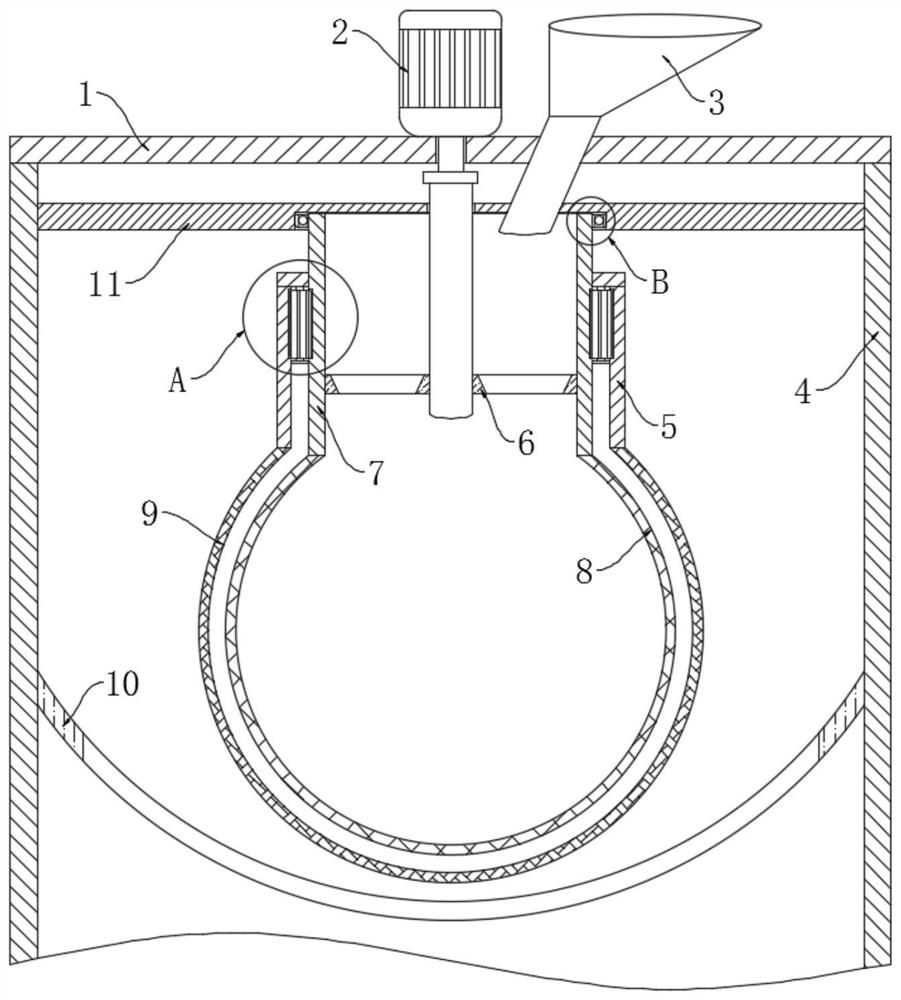
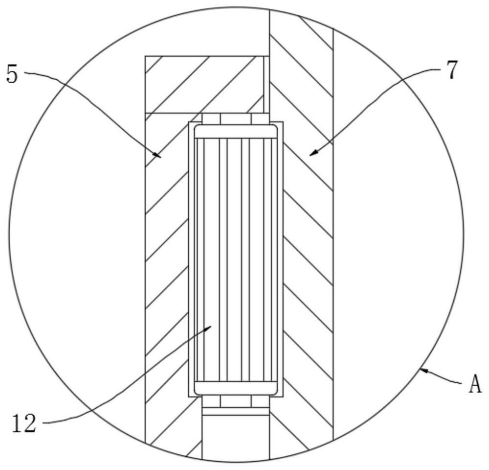
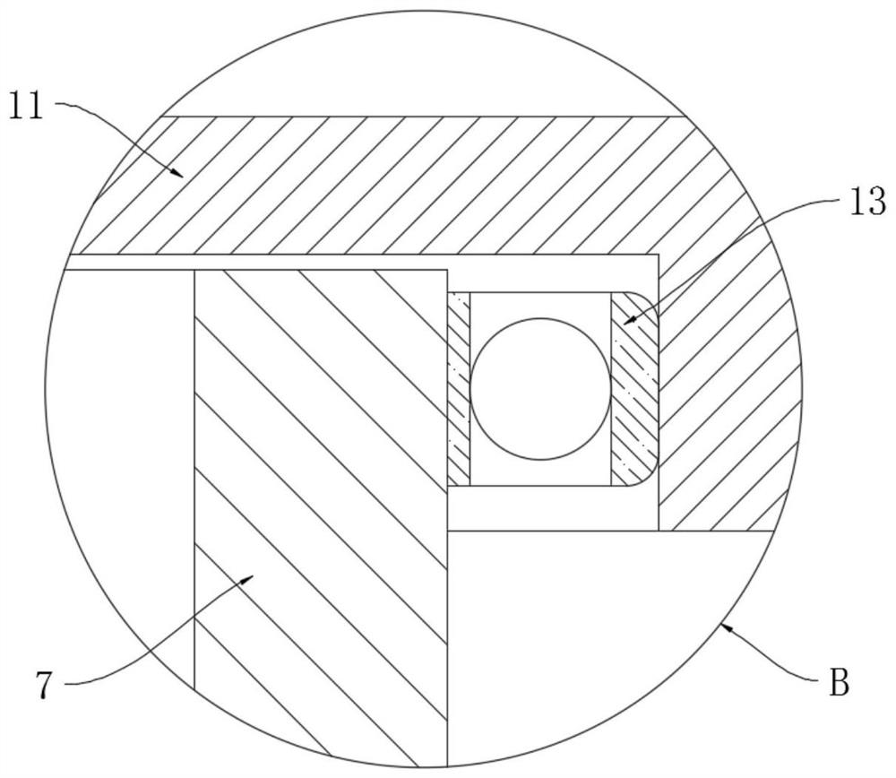
[0028] refer to Figure 1-4 , a slurry device for preparing bio-organic water and fertilizer, comprising a shell 4 and a cover plate 1 fixed above the shell 4, the cover plate 1 and the shell 4 are fixed by bolts to facilitate the disassembly of the cover plate 1 and the Installation, the housing 4 is coaxially provided with a first connecting cylinder 5 and a second connecting cylinder 7, and the inner diameter of the first connecting cylinder 5 is greater than the outer diameter of the second connecting cylinder 7, and the inner side wall of the first connecting cylinder 5 and The outer side walls of the second connecting cylinder 7 are provided with tooth grooves, and a plurality of reversing gears 12 are meshed between the two tooth grooves. The lower ends of the first connecting cylinder 5 and the second connecting cylinder 7 are respectively fixedly connected with outer crushing layer 9 and inner crushing layer 8;
[0029] The drive motor 2 is fixedly installed on the c...
Embodiment 2
[0038] refer to Figure 5 , the present embodiment differs from Embodiment 1 in that the inner crushing layer 8 is made of a rigid ferromagnetic filter, the outer crushing layer 9 is made of a flexible metal mesh, and the diameter of the mesh of the rigid ferromagnetic filter is larger than that of the flexible The mesh diameter of the metal mesh sheet is symmetrically distributed with a plurality of magnetic blocks 14 on the outer wall of the outer pulverized layer 9, and the outer side of the magnetic block 14 is wrapped with an anti-wear sheet to avoid damage to the magnetic block 14 caused by the high-speed moving slurry.
[0039] When the present embodiment is in use, the magnetic block 14 and the inner crushed layer 8 attract each other under the action of a magnetic field, so the magnetic block 14 will make the outer crushed layer 9 approach the inner crushed layer 8, and the gap between the two becomes smaller, and the outer crushed layer 9 The pressure on the small lu...
Embodiment 3
[0041] refer to Image 6 The difference between this embodiment and Embodiment 1 is that the inner crushing layer 8 is made of a ferromagnetic grinding mesh, the outer crushing layer 9 is made of a stainless steel grinding mesh, and the lower end of the first connecting cylinder 5 is rotatably installed by a second bearing 15 There is a hemispherical cover body 16, and the hemispherical cover body 16 comprises an upper cover layer and a lower filter layer, two magnetic strips 17 are symmetrically arranged on the outer sidewall of the upper cover layer, and the nets of the inner crushed layer 8, the outer crushed layer 9 and the lower filter layer The hole diameters decrease in order.
[0042] When this embodiment is in use, the gap between the inner crushing layer 8, the outer crushing layer 9 and the hemispherical cover 16 maintains a fixed width, and the inner crushing layer 8 and the outer crushing layer 9 rotate in opposite directions because the hemispherical cover 16 pas...
PUM
 Abstract
Description
Claims
Application Information
 - R&D
- Intellectual Property
- Life Sciences
- Materials
- Tech Scout
- Unparalleled Data Quality
- Higher Quality Content
- 60% Fewer Hallucinations
Browse by: Latest US Patents, China's latest patents, Technical Efficacy Thesaurus, Application Domain, Technology Topic, Popular Technical Reports.
© 2025 PatSnap. All rights reserved.Legal|Privacy policy|Modern Slavery Act Transparency Statement|Sitemap|About US| Contact US: help@patsnap.com


