
Electrified railway traction emergency guarantee power supply system and control method

A technology for traction power supply systems and electrified railways. It is applied in power lines, photovoltaic power generation, transportation and packaging, etc. It can solve the problems of short power supply time of on-board emergency power supplies, failure to take power normally, and high requirements for forward transmission capacity.

Active Publication Date: 2020-10-16
SOUTHWEST JIAOTONG UNIV
View PDF26 Cites 10 Cited by
  • Summary
  • Abstract
  • Description
  • Claims
  • Application Information

AI Technical Summary

Problems solved by technology

[0003]In summary, railway systems often face many problems in harsh service environments: 1) The particularity of lines caused by harsh service environments places extremely high requirements on the reliability of power supply for traction power supply systems However, the overall external power grid of this type of line is often extremely weak. In addition, in the structure of the existing traction power supply system, there is no backup traction network system from the low-voltage 27.5kV feeder to the traction load. Difficult service environment, once the external power supply (main / standby) or traction network fails, the train will not be able to take power normally, how to meet the power demand of life support equipment such as the train’s oxygen generation system / air conditioning and ventilation system, and maintain the self-propelled train capacity, which is related to the safety of passengers, especially in the high cold plateau, the thin air in the long tunnel, and the harsh weather conditions; High requirements for forward transmission capacity, large demand for traction transformer capacity, sudden drop in network voltage, power quality (reactive power / negative sequence / harmonic) caused by positive asymmetrical power flow, etc. Similarly, traction in the long downhill direction The power supply system will also face related problems such as reverse large current carrying, network voltage surge, and reverse power flow quality caused by braking current, and the above-mentioned completely opposite load characteristics will bring serious problems to the design of traction power supply system and external power grid. Challenges; 3) The traction load of railways in harsh service environments is generally heavy, and the requirements for the power supply capacity of traction substations in the uphill direction are often higher than those of ordinary railways, so the demand for system power supply capacity is huge. A series of alternating high-power source-load double impact and uncertainty issues will bring more severe challenges to the already extremely fragile external power grid
At present, the vehicle-mounted emergency power supply in the existing emergency support power supply technology has a short power supply time, and it is difficult to meet the self-propelled ability required in complex railways; at the same time, there is no ground-type traction emergency support power supply system that can be independent of the traction power supply system.
In addition, the difficulty of implementing conditions for complex railway projects also determines that the electrification system of the peripheral equipment should have the construction requirements of simplicity, integration, and multi-functional integration, but the existing power supply system is difficult to meet the above requirements at the same time

Method used


Image

  • Electrified railway traction emergency guarantee power supply system and control method
  • Electrified railway traction emergency guarantee power supply system and control method
  • Electrified railway traction emergency guarantee power supply system and control method

Examples


Embodiment Construction

[0051] In order to make the purpose, technical solution and advantages of the present invention clearer, the present invention will be further elaborated below in conjunction with the accompanying drawings.

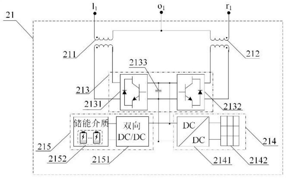
[0052] In this example, see figure 1 As shown, the present invention proposes an electrified railway traction emergency guarantee power supply system, including a phase-splitting traction power supply system 1 and an energy routing conversion system 2;

[0053] The phase-splitting traction power supply system 1 includes multi-stage traction transformer substations TS12.13.14; each traction transformer substation TS adopts a phase-sequence rotation method. The independent power supply arm 17 divided by 15 sub-phases of the transformer substation is connected to supply energy for the traction load; the traction load is a train 19 with a vehicle-mounted emergency power supply 20; a partitioned sub-phase substation is set between adjacent traction transformer substations TS ...


PUM


Abstract

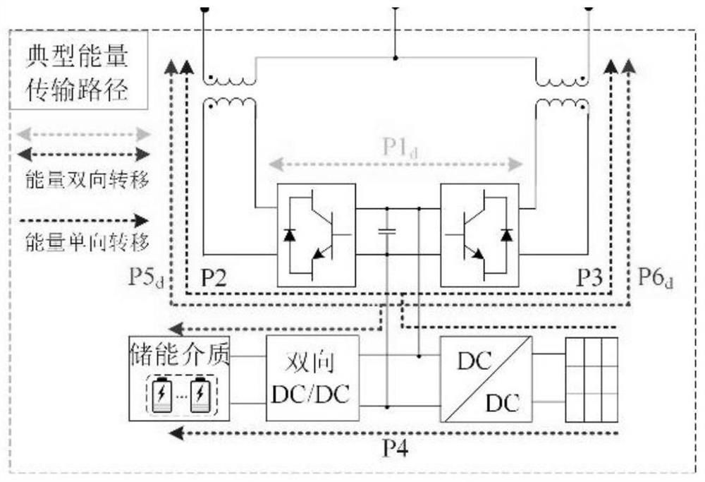
The invention discloses an electrified railway traction emergency guarantee power supply system and a control method. The system comprises a split-phase traction power supply system and an energy routing conversion system. The split-phase traction power supply system comprises multiple sections of traction transformation stations; each traction transformation station adopts an alternating phase sequence wiring method, a primary side takes electricity from a power grid, and a secondary side is connected with an independent power supply arm divided by transformation station electricity split phases to supply power to a traction load; subarea station electric split phases are arranged between the adjacent traction transformation stations; an internal energy conversion device modular unit is arranged at each traction substation in a bridging manner; an inter-energy conversion device modular unit is arranged at the electric split-phase position of a section post between every two adjacent traction substations in a bridging mode, and the internal energy conversion device modular units and the inter-energy conversion device modular units are subjected to unified energy management and coordination control through a central controller. The power supply reliability and flexibility of the traction power supply system in a severe service environment can be effectively improved.

Description

technical field [0001] The invention belongs to the technical field of electrified railways, and in particular relates to a traction emergency guarantee power supply system and a control method for electrified railways. Background technique [0002] For railway projects that are difficult to construct, high in risk, and operating in a difficult and dangerous environment, such as the "eight ups and downs" of the entire line section of the Sichuan-Tibet Railway, the cumulative climb and fall are all over 10,000 meters, and the external power grid along the line is extremely weak and a high proportion of oversized Multiple complex and systematic difficulties such as tunnels, super-long ramps, plateaus and high temperatures, and strong sunshine will make the railway traction power supply system face great challenges. Therefore, when faced with such complex lines, in order to fully ensure the reliable power supply of the system, the demand for traction emergency support power sup...

Claims


Application Information

Patent Timeline
IPC IPC(8): B60M3/00
CPCB60M3/00Y02E10/56
Inventor 戴朝华邓文丽
Owner SOUTHWEST JIAOTONG UNIV
Learn More