Device and process for decarburization of gas containing high-concentration CO2 and regeneration of amine liquid

An amine liquid and gas technology, which is applied in the field of devices for decarburization of high-concentration CO2 gas and regeneration of amine liquid, which can solve the problems of large loss rate and the like

Pending Publication Date: 2020-10-30
XINDI ENERGY ENG TECH
View PDF0 Cites 3 Cited by
  • Summary
  • Abstract
  • Description
  • Claims
  • Application Information

AI Technical Summary

Problems solved by technology

Although the membrane separation method has the advantages of low energy consumption, small floor space, convenient maintenance, h

Method used


Image

  • Device and process for decarburization of gas containing high-concentration CO2 and regeneration of amine liquid

Examples


Embodiment 1

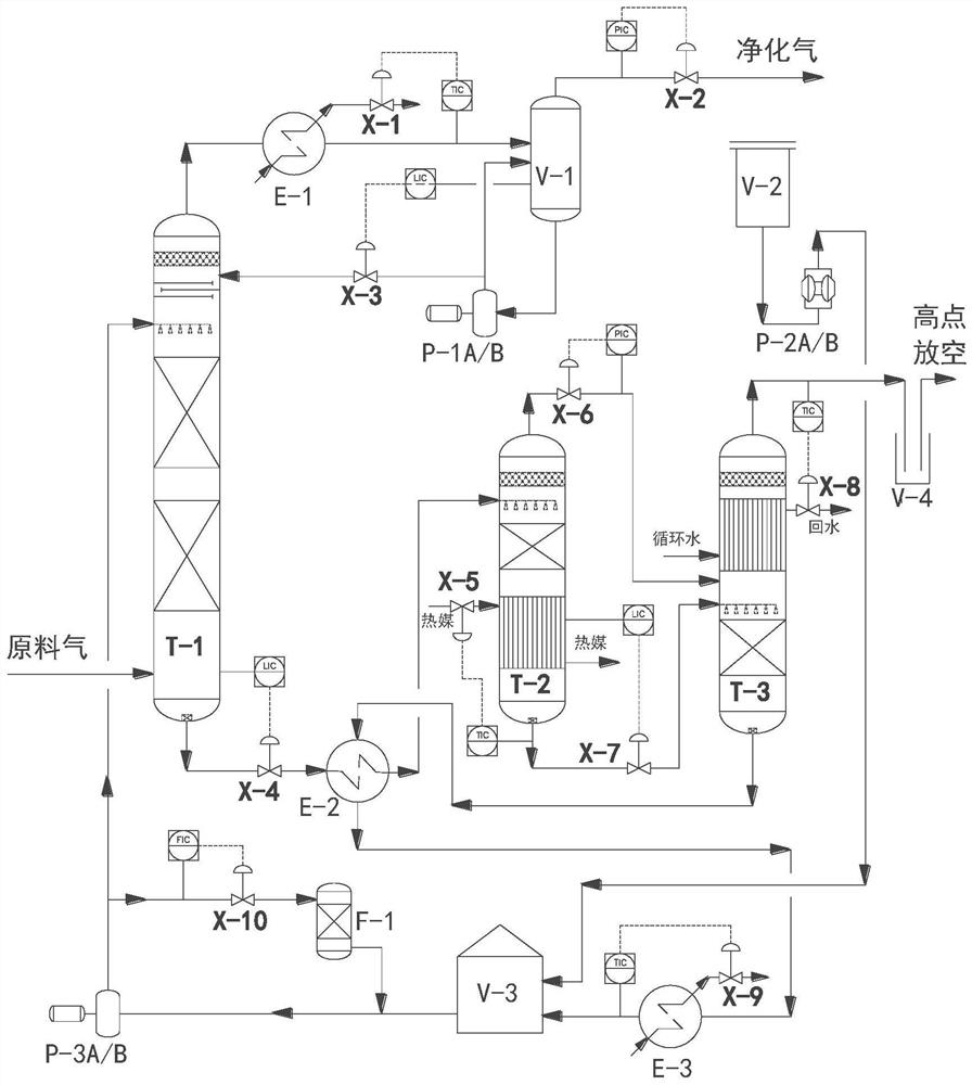
[0056] (1)CO 2 Absorption: Natural gas with a carbon content of 25% (mole%) and a temperature of about 40°C (the component of the high-acid feed gas is mainly CH 4 , CO 2 , additionally contains a small amount of H 2 or N 2 ) enters from the bottom of the absorption tower T-1, and flows from bottom to top; amine liquid (about 35wt% MDEA aqueous solution) at about 46°C pours from the upper part of the absorption tower T-1 (the volume of high-acid raw material gas and amine liquid The flow ratio is about 30:1), passing through the absorption tower T-1 from top to bottom, after the counter-flowing amine liquid and natural gas fully contact the heat and mass transfer in the tower, the CO in the natural gas 2 Absorbed by amine liquid, output CO from the top of the absorption tower 2 Purified gas whose concentration is reduced to below 2.5% (mole%).

[0057] (2) The purified gas output from the top of the absorption tower T-1 is cooled by the purified gas cooler E-1 (usually to...

Embodiment 2

[0063] (1)CO 2 Absorption: carbon content or CO 2 Synthesis gas with a content of 35% (mole%) and a temperature of about 40°C (the components of the high-acid feed gas are mainly CH 4 , CO 2 , additionally contains a small amount of H 2 or N 2 ) enters from the bottom of the absorption tower T-1, and flows from bottom to top; lean amine liquid (concentration is about 35wt% MDEA aqueous solution; amine liquid spray density is 15-20m 3 / m 2 * between h) from the upper part of the absorption tower T-1 (the volume flow ratio of the high-acid raw material gas to the amine liquid is about 27:1), and pass through the absorption tower T-1 from top to bottom, and the reverse flow of the amine liquid and After the natural gas is fully exposed to heat and mass transfer in the tower, the CO in the natural gas 2 Absorbed by amine liquid, output CO from the top of the absorption tower 2 Purified gas whose concentration is reduced to below 2.5% (mole%).

[0064] (2) The purified gas ...


PUM


Abstract

The invention discloses a device and a process for decarburization of gas containing high-concentration CO2 and regeneration of amine liquid. The device comprises an absorption tower, an amine liquidprimary flash tower, an amine liquid secondary flash tower, a purified gas cooler, a lean/rich amine liquid heat exchanger, a lean amine liquid cooler, an amine liquid filter, an absorption tower cleaning pump, a charging pump, an amine liquid circulating pump, a purified gas-liquid separator, a charging tank, a solution buffer tank, a liquid seal tank and a regulating valve. The device is suitable for the process for regenerating the amine liquid after decarburization of high-acid natural gas or synthetic gas with the acid gas content of 35% (mol%), and the carbon content of the purified gasis controlled to be not higher than 2.5% (mol%). According to the device, the amine liquid primary flash tower and the amine liquid secondary flash tower are used for replacing a regeneration tower, only part of heat is provided for the lower portion of the primary flash tower, the heat taking amount is greatly reduced, and energy consumption of the device is reduced; a traditional amine-rich liquid flash tank is replaced by the primary flash tower, and a carbon dioxide gas-liquid separator and a regeneration tower reflux pump do not need to be arranged in the process due to the secondary flash tower, so that the quantity of equipment is greatly reduced, and the process is greatly simplified.

Description

technical field [0001] The invention relates to a device and process for decarburization and amine liquid regeneration, in particular to a high-concentration CO 2 Device and process for gas decarburization and amine liquid regeneration, suitable for CO in natural gas or syngas 2 In the process of gas decarbonization treatment with content ≤35% (mole%), CO in the purified gas after treatment 2 Content <2.5% (mole%). Background technique [0002] Syngas and natural gas produced from formations usually contain some CO 2 and other acid gases. According to my country's commodity natural gas index requirements, CO 2 The content needs to be less than 3% (mole%) to be exported to civilian users, so high CO content 2 Natural gas needs to be decarbonized. At present, the commonly used decarbonization methods at home and abroad include low temperature separation method, membrane separation method, adsorption separation method, solvent absorption method, and the combined separa...

Claims


Application Information

Patent Timeline
IPC IPC(8): C10L3/10B01D53/18B01D53/14B01D3/06B01D3/42
CPCB01D3/065B01D3/42B01D53/1475B01D53/18B01D2252/204C10L3/104Y02P70/10
Inventor 张晓哲李占越李翠王立森杨涛杨立雨邓巍巍张帅贾田刚吴海燕任冬波宋志波
Owner XINDI ENERGY ENG TECH
Why Eureka
Try Eureka