Fabric stripping device for textile processing and stripping method of fabric stripping device

A fabric and color stripping technology, which is applied in textile processing machine accessories, textile material processing equipment configuration, textile material processing, etc., can solve the problems of affecting the stripping effect, fabric color cannot be separated, and low efficiency

Inactive Publication Date: 2020-10-30
宣城红妆美人床上用品有限公司
View PDF4 Cites 0 Cited by
  • Summary
  • Abstract
  • Description
  • Claims
  • Application Information

AI Technical Summary

Problems solved by technology

[0003] Nowadays, the color stripping of fabrics in the textile processing process requires the contact reaction between the reducing agent and the dyes on the fabrics to remove the color on the fabrics. Generally, the fabrics are conveyed directly by conveying rollers, or by pressing rollers. Directly press the fabric into the reducing agent for soaking and stripping, or produce reducing agent gas by heating for contact stripping, but the efficiency of direct soaking and stripping is low, and the heated reducing agent gas will make the fabric localized due to the high temperature. Wrinkles caused by temperature difference, resulting in the inability to separate the color of some fabrics and affecting the actual stripping effect

Method used


Image

  • Fabric stripping device for textile processing and stripping method of fabric stripping device
  • Fabric stripping device for textile processing and stripping method of fabric stripping device
  • Fabric stripping device for textile processing and stripping method of fabric stripping device

Examples


Embodiment 1

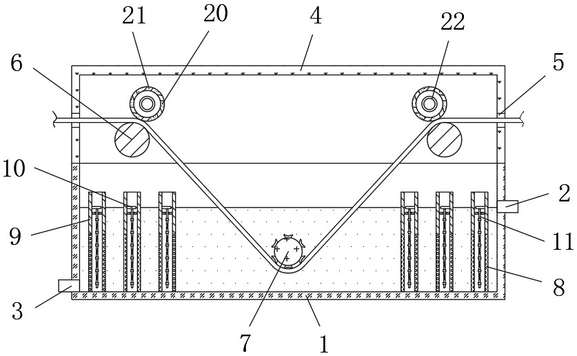
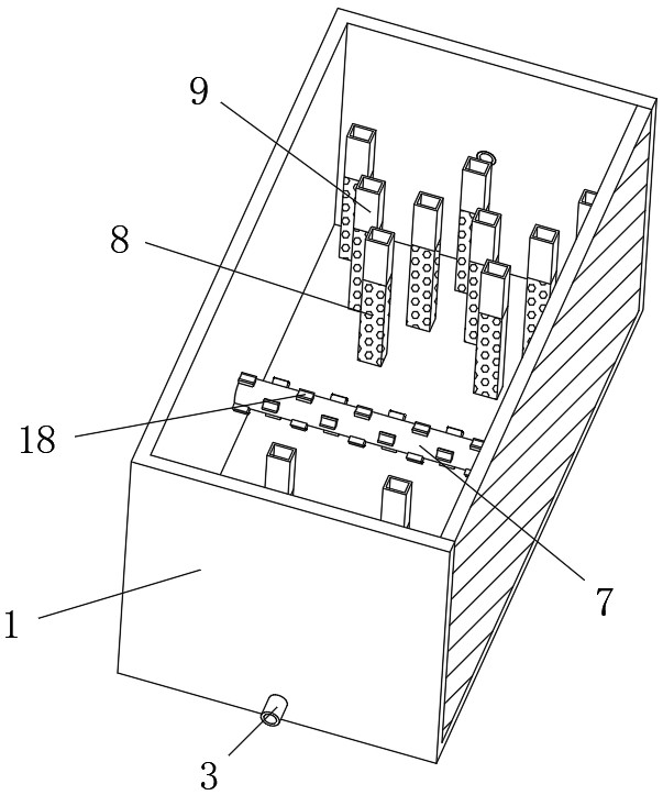
[0032] refer to Figure 1-5 , a fabric stripping device for textile processing, comprising a treatment box 1, the two sides of the treatment box 1 are respectively fixed with a liquid inlet pipe 2 and a liquid outlet pipe 3, and the liquid inlet pipe 2 is located above the liquid outlet pipe 3, and the treatment box The top of 1 is fixed with a cover box 4, and both sides of the cover box 4 are provided with through grooves 5, and both sides between the inner walls of the two ends of the cover box 4 are rotatably connected with support rollers 6, and the inner walls of the two ends of the treatment box 1 The middle position of the bottom of the space is rotatably connected with a pressure roller 7, and the top of the outer wall of the support roller 6 and the bottom of the outer wall of the pressure roller 7 are rotatably connected with a fabric, and the fabric moves toward the side close to the liquid inlet pipe 2, and the two sides of the inner wall of the bottom of the treat...

Embodiment 2

[0040] refer to Figure 1-6 , a fabric stripping device for textile processing, the circumferential outer wall of the pressing roller 7 is fixed with abutting blocks 18 equidistantly distributed, and the abutting blocks 18 are arranged at intervals, and the abutting blocks 18 are arranged on the outer wall of one side away from the pressing roller 7 It forms an arc-shaped structure that arches outwards. The outer wall of the block 18 away from the pressure roller 7 is provided with a filling groove 19 that penetrates at both ends. The inner wall of the filling groove 19 is arranged in an arc-shaped structure. In the process of relative rotation, the fabric is squeezed into the low-end filling groove 19 due to the stretching force, and the liquid in the filling groove 19 is squeezed out to increase the local liquid flow and improve the liquid and fabric and the block 18. Peeling effect at the contact position of the outer wall;

[0041] The position corresponding to the suppor...

Embodiment 3

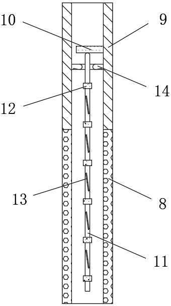
[0044] refer to Figure 1-6 , a stripping method of a fabric stripping device for textile processing, comprising a treatment box 1, a liquid inlet pipe 2, a liquid outlet pipe 3, a support roller 6, a pressure roller 7, a fixed net cylinder 8, a connecting cylinder 9 and an atomizing vibration The sheet 10 also includes an auxiliary rod located in the fixed mesh cylinder 8, and a block 18 located on the outer wall of the pressure roller 7. The fabric in the middle position is immersed in the liquid medicine by the pressure roller 7 for soaking and stripping, while the two sides are connected. The liquid medicine in the cylinder 9 is relatively static so that the liquid medicine is atomized by the atomizing vibrating plate 10, and the atomized liquid medicine rises and contacts the fabric to improve the color stripping effect, and avoid the partial temperature difference wrinkling of the fabric caused by heating up. The color stripping is not complete, and the chemical solution...


PUM


Abstract

The invention discloses a fabric stripping device for textile processing and a stripping method of the fabric stripping device. The device comprises a processing box, a liquid inlet pipe and a liquidoutlet pipe are separately fixed to two sides of the processing box, the liquid inlet pipe is located above the liquid outlet pipe, a covering box is fixed to the top of the processing box, and penetrating grooves are formed in two sides of the covering box; and two sides between the inner walls of two ends of the covering box are rotatably connected with a back-up roll, and the bottom middle position between the inner walls of two ends of the processing box is rotatably connected with a pressure roller, and the top of the outer wall of the back-up roller and the bottom of the outer wall of the pressure roller are rotatably connected with the fabric. The stripping method comprises the steps that an atomizing vibration plate is used for atomizing liquid medicine, the atomized liquid medicine is raised to be in contact with the fabric for stripping, and the atomizing vibration plate is used for performing vibration transmission on the liquid medicine at the bottom of the processing box.The atomizing vibration plate is used for atomizing the liquid medicine, and the atomizing vibration plate is used for performing vibration transmission on the liquid medicine to increase the fluctuation of the liquid medicine so as to improve the stripping effect of fabric the immersed in the liquid medicine.

Description

technical field [0001] The invention relates to the technical field of textiles, in particular to a fabric stripping device and a stripping method for textile processing. Background technique [0002] The original meaning of textile is taken from the general term of spinning and weaving, but with the continuous development and improvement of the textile knowledge system and subject system, the current textile is not only the traditional hand spinning and weaving, but also non-woven technology. Modern three-dimensional weaving technology, modern textile refers to a multi-scale structure processing technology of fibers or fiber aggregates. During the production and processing of textile technology, dyeing and processing of fabrics are used to make finished products, often in the process of dyeing fabrics. There will be errors in the process and the fabric needs to be stripped and reprocessed. [0003] Nowadays, the color stripping of fabrics in the textile processing process ...

Claims


Application Information

Patent Timeline
Patent Type & Authority Applications(China)
IPC IPC(8): D06B13/00D06B23/02D06B23/20
CPCD06B13/00D06B23/021D06B23/026D06B23/025D06B23/20
Inventor 程秀玲覃立宽
Owner 宣城红妆美人床上用品有限公司
Why Eureka
Try Eureka