
Coil winding, transformer and series-parallel power electronic device

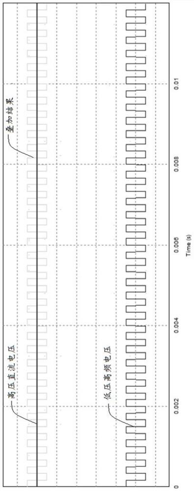
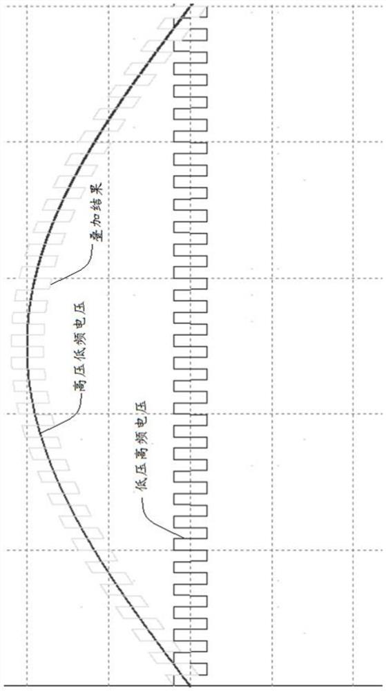
A coil winding and transformer technology, which is applied to transformer/inductor components, transformer/inductor coil/winding/connection, output power conversion devices, etc. Increase the dielectric loss and other problems, to achieve the effect of high thermal conductivity, reduce dielectric loss, and improve thermal conductivity

Active Publication Date: 2020-10-30
SUNGROW POWER SUPPLY CO LTD
View PDF11 Cites 4 Cited by
  • Summary
  • Abstract
  • Description
  • Claims
  • Application Information

AI Technical Summary

Problems solved by technology

[0004] However, the insulating material in the existing overall pouring scheme has certain coupling in its dielectric strength, dielectric loss, thermal conductivity and other parameters. If the insulating material is required to achieve better performance in various aspects, then will be more difficult
In the intermediate frequency transformer, there are high frequency and high voltage at the same time, and the electric field shielding layer is added around the winding to solve the insulation defect, but this will increase the local high frequency dielectric loss.
If the selected insulating material has a low dielectric loss, it means that the thermal conductivity is low. If the selected insulating material has a good thermal conductivity, it may increase the dielectric loss. Therefore, the transformer cannot balance low dielectric loss and High thermal conductivity

Method used


Image

  • Coil winding, transformer and series-parallel power electronic device
  • Coil winding, transformer and series-parallel power electronic device
  • Coil winding, transformer and series-parallel power electronic device

Examples


Embodiment Construction

[0039] In order to make the purpose, technical solutions and advantages of the embodiments of the present invention clearer, the technical solutions in the embodiments of the present invention will be clearly and completely described below in conjunction with the drawings in the embodiments of the present invention. Obviously, the described embodiments It is a part of embodiments of the present invention, but not all embodiments. Based on the embodiments of the present invention, all other embodiments obtained by persons of ordinary skill in the art without making creative efforts belong to the protection scope of the present invention.

[0040] In this application, the term "comprises", "comprises" or any other variation thereof is intended to cover a non-exclusive inclusion such that a process, method, article, or apparatus comprising a set of elements includes not only those elements, but also includes none. other elements specifically listed, or also include elements inher...


PUM


Abstract

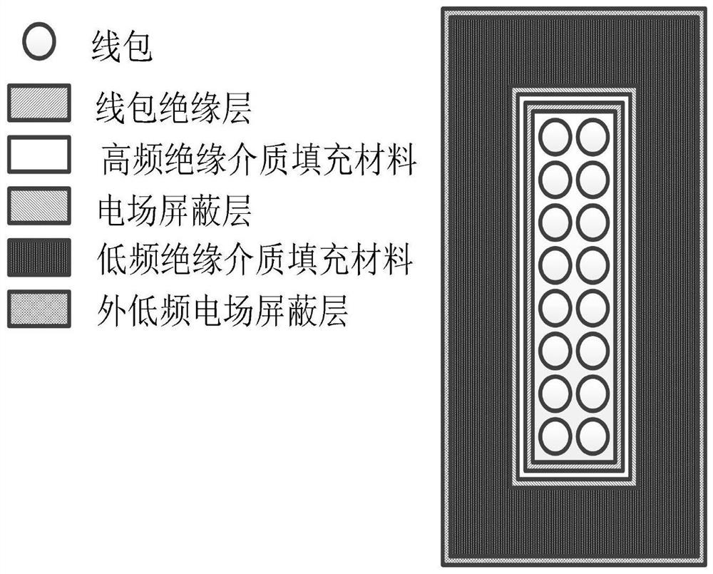
The invention provides a coil winding, a transformer and a series-parallel power electronic device, and the coil winding is characterized in that a coil insulating layer wraps the outer side of a coilunit, then the inner side of an electric field shielding layer is filled with a high-frequency insulating medium filling material, and then the outer side of the electric field shielding layer is filled with a low-frequency insulating medium filling material; a high-frequency insulating medium filling material and a low-frequency insulating medium filling material are used, wherein one is a filling material with a dielectric loss angle and / or a dielectric constant lower than a corresponding preset low threshold value, dielectric loss can be reduced, and local high-frequency dielectric loss aggravation caused by an electric field shielding layer is made up, the other one is a filling material with a dielectric loss angle and / or a dielectric constant higher than a corresponding preset highthreshold value, so that the heat conduction performance can be improved, the temperature rise can be reduced, and the heat dissipation can be ensured, so the two parameters with the coupling relationship can be optimized, and the low dielectric loss and the high heat conduction performance can be considered at the same time.

Description

technical field [0001] The invention belongs to the technical field of power electronics, and more specifically relates to a coil winding, a transformer and a series-parallel power electronic device. Background technique [0002] Between the primary and secondary sides of the intermediate frequency transformer of the power electronic transformer, the voltage difference has both high voltage and high frequency components; in the structure of cascaded power electronic transformers, generally speaking, the high voltage is low frequency or even DC components, while the high frequency The composition is low pressure. Therefore, in order to achieve better insulation performance, solid insulation is generally used. [0003] In current applications, there are two types of high-voltage casting transformers. One is the traditional dry-type transformer. The primary and secondary coils are cast separately and then installed into insulating sleeves, insulating pads, and iron cores. The...

Claims


Application Information

Patent Timeline
IPC IPC(8): H01F27/32H01F27/36H01F27/30H01F27/28H02M3/335
CPCH01F27/324H01F27/306H01F27/2876H02M3/33569Y02E10/76
Inventor 庄加才徐君赵玉顺蔡国庆刘威
Owner SUNGROW POWER SUPPLY CO LTD
Learn More