CRM buck-boost converter controlled by segmented constant conduction time

A buck-boost converter and time control technology, which is applied in the control/regulation system, output power conversion device, DC power input conversion to DC power output, etc., can solve the problem of poor EMI differential mode characteristics and large conduction loss of switching tubes , Inductive current peak value and other problems, to achieve the effect of small conduction loss, reduce inductor current ripple, and reduce current effective value

Active Publication Date: 2020-10-30
NANJING UNIV OF SCI & TECH
View PDF4 Cites 3 Cited by
  • Summary
  • Abstract
  • Description
  • Claims
  • Application Information

AI Technical Summary

Problems solved by technology

Although Boost PFC is an effective way to improve power factor and reduce current harmonics, the large loss at low-voltage input is a bottleneck restricting its development, while Buck PFC has the characteristics of step-down of the Buck circuit itself, so that the input and output The voltage is relatively close, so that it can maintain high efficiency in the entire input voltage range. In addition, Buck PFC has the advantages of low output voltage, low common-mode EMI noise, no surge limiter and small main inductance. PFC has gradually become a research hotspot in power factor correction technology
[0003] However, there is an inherent dead zone in the Buck PFC converter, that is, the cir

Method used


Image

  • CRM buck-boost converter controlled by segmented constant conduction time
  • CRM buck-boost converter controlled by segmented constant conduction time
  • CRM buck-boost converter controlled by segmented constant conduction time

Examples


Example Embodiment

[0034] The present invention will be further described in detail below in conjunction with the drawings and specific embodiments.

[0035] 1 The working principle of CRM Buck-Buck / Boost PFC converter

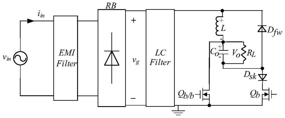
[0036] figure 1 It is the main circuit of CRM Buck-Buck / Boost PFC converter.

[0037] Settings: 1. All devices are ideal components; 2. The output voltage ripple is very small compared to its DC value; 3. The switching frequency is much higher than the input voltage frequency.
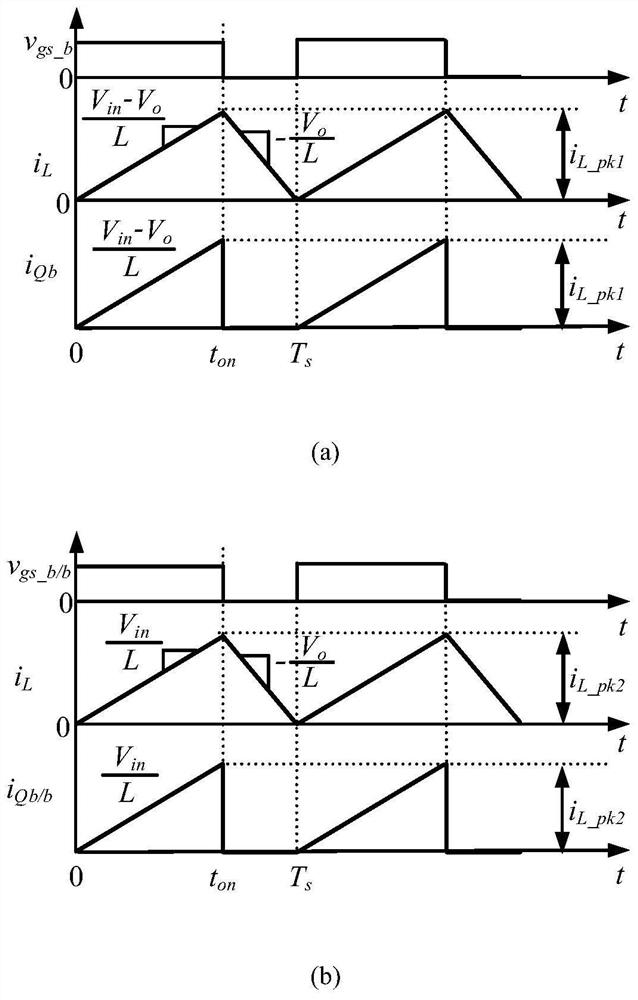
[0038] figure 2 The waveforms of the switch tube current and inductor current in a switching cycle of the CRM Buck-Buck / Boost PFC converter are given. The figure (a) is the waveform of the Buck converter while the figure (b) is the Buck / Boost converter. Waveform diagram at work. When the input voltage v g Less than the output voltage V o 时,The second switch tube Q b / b When conducting, D fw Cut off, the voltage across the inductor L is v g , Its current i L Start from zero with v g The slope of / L increases ...


PUM


Abstract

The invention discloses a CRM buck-boost converter controlled by segmented constant conduction time. The converter comprises a main power circuit and a control circuit, wherein the control circuit comprises an input voltage feed-forward circuit, a first multiplier, an RS trigger, a comparator, a first gating switch, a switching signal generation circuit, an output voltage feedback circuit, an ANDgate and NOT gate, a switching tube driving circuit and an output voltage sampling circuit; and the control circuit generates a control signal according to input voltage feedforward and output voltagefeedback of the main power circuit; two switching tubes in the main power circuit are driven to work, so that the conduction time of the converter working in the Buck stage and the conduction time ofthe converter working in the Buck/Boost stage in one power frequency period are different, the input current is closer to sine waves with the same phase as the input voltage, and the PF value is increased in the input voltage range. According to the invention, the power factor of the converter is improved, and the converter has the advantages of being small in inductive current peak value, smallin switching tube conduction loss and small in required diode stress.

Description

technical field [0001] The invention relates to the technical field of AC-DC converters of electric energy conversion devices, in particular to a control method for segmental constant conduction time of a CRM step-down-boost-boost converter. Background technique [0002] A power factor correction (Power Factor Correction, PFC) converter can reduce input current harmonics and improve input power factor, and has been widely used. PFC converters are divided into active and passive methods. Compared with passive methods, the active method has the advantages of high input power factor, small size, and low cost. Since its development in the 1980s, scholars from various countries have conducted in-depth research on active power factor correction technology (APFC) from the perspectives of control strategy, circuit topology, and small signal modeling, and have achieved a series of research results. For now, a new research focus of APFC technology is the research on PFC circuit topol...

Claims


Application Information

Patent Timeline
IPC IPC(8): H02M1/42H02M1/44H02M3/158H02M7/217
CPCH02M1/4233H02M1/44H02M3/1582H02M7/217H02M1/0048Y02B70/10
Inventor 陈杰楠姚凯马春伟张震邬程健管婵波李凌格方斌
Owner NANJING UNIV OF SCI & TECH
Why Eureka
Try Eureka